Note/IllustrationAction
Fix the wrist with two screws and two washers. Re-
move the M8 guide pins and fit the other two screws
and washers.
5
Connect to motor axis 5, connect-
or R3.MP5:
• + :pin 7
• -: pin 8
Connect to motor axis 6, connect-
or R3.MP6:
• + : pin 7
• -: pin 8
In order to release the brakes, connect the 24 VDC
power supply to the motor.
Note! Release the brakes of the two motors, but one
at a time!
6
Art. no. is specified in Required
equipment on page 135.
Fit the measuring tool at the rear of the motor.7
xx0200000425
Push the wrist, as shown in the figure to the right,
to locate the smallest play in the same way as for
adjustment of play when changing motors for axes
5 and 6, detailed in section Replacement of motors,
axes 4-6, IRB 2400/10/16 on page 190.
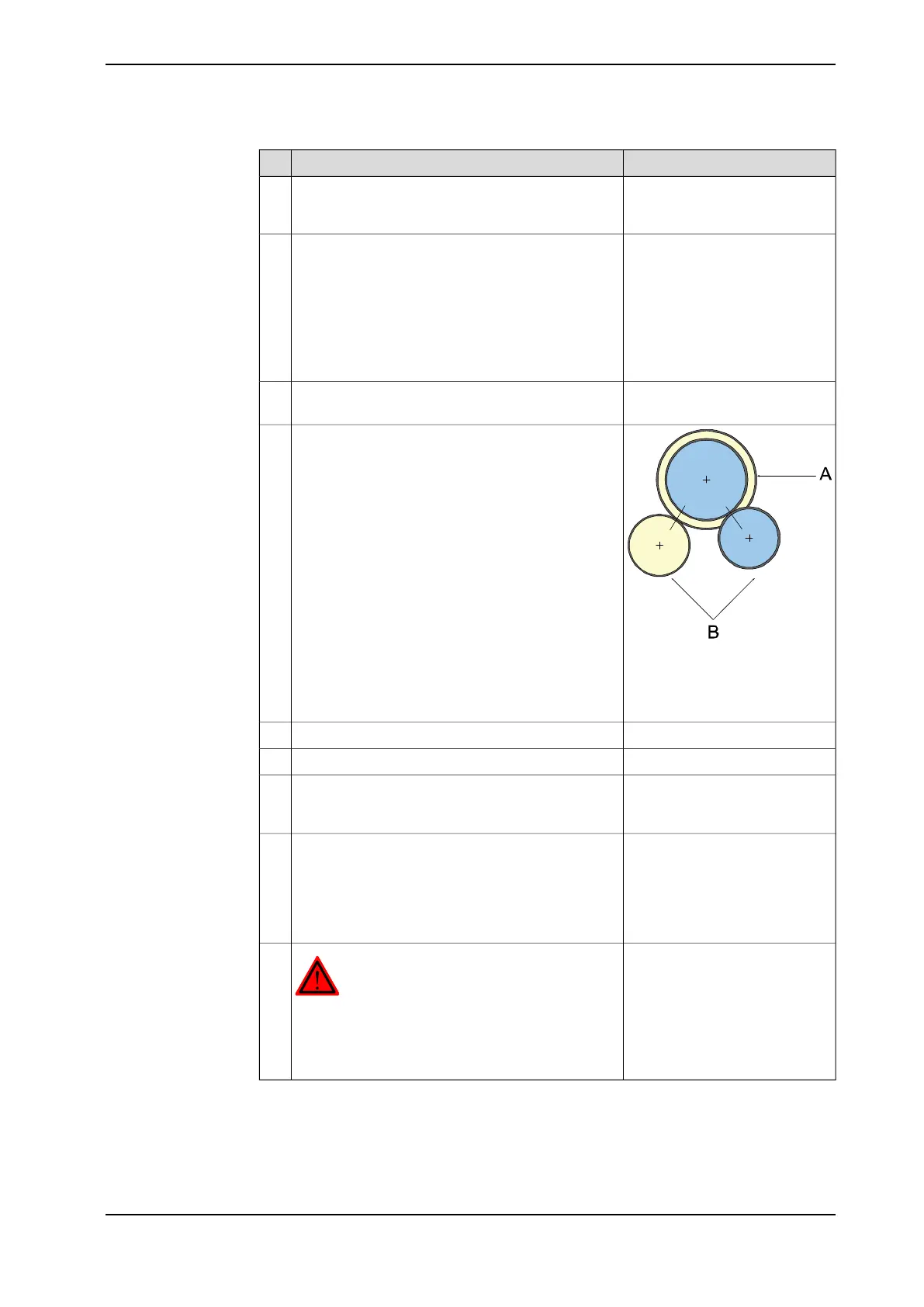
8
A Gears on drive shaft unit,
axis 5-6
B Gears on the wrist
Tightening torque: 17 Nm.Tighten the attachment screws and washers.9
Check the play by moving axes 5 and 6 by hand.10
This is detailed in section Oil
change, gearbox axes 5-6 (wrist
unit) on page 93.
Refill the wrist unit with oil.11
Calibration is detailed in a separ-
ate calibration manual enclosed
with the calibration tools.
Recalibrate the robot.12
General calibration information
is included in the section Calibra-
tion information on page 205.
DANGER
Make sure all safety requirements are met when
performing the first test run. These are further de-
tailed in the section First test run may cause injury
or damage on page 29.
13
Product manual - IRB 2400 137
3HAC022031-001 Revision: P
© Copyright 2004-2018 ABB. All rights reserved.
4 Repair
4.4.1 Replacement of wrist IRB 2400/10/16
Continued

 Loading...


