
 Loading...
Do you have a question about the ABB IRB 2400/10 and is the answer not in the manual?
Explains the manual's content and purpose, including instructions for installation, maintenance, and repair.
Outlines the structure and content of each chapter, detailing the scope of information provided.
Lists other relevant ABB manuals and documentation for further information on robot systems.
Details the changes and updates made in different versions of the product manual.
Explains how to interpret and follow procedural steps, including references to figures and equipment.
Highlights the importance of safety information and where to find critical safety warnings.
Lists the typical contents of product manuals for M2000 robot systems, covering installation, maintenance, and repair.
Details the general content of product manuals for ABB Robotics products, including safety and installation.
Explains the purpose and content of manuals for specific applications or hardware options.
Covers fundamental safety principles, including limitation of liability and nation-specific regulations.
Clarifies ABB's responsibility for safety and potential causes of injury or damage.
Details various safety hazards encountered during installation, service, and operational disturbances.
Warns about the dangers of robot movement and necessary precautions for safe handling.
Introduces assembly and installation procedures for the IRB 2400 at the working site.
Guides through the initial unpacking and pre-installation checks of the robot.
Lists essential checks and prerequisites required before installing the robot.
Specifies the operational areas and positions for robot models, illustrated with diagrams.
Provides procedures for installing the robot at its operational site, including lifting and securing.
Explains how to release robot axis brakes using the internal brake release unit.
Guides on correctly positioning and fastening the robot to its foundation using attachment screws.
Covers the procedure for installing the robot in an upside-down configuration.
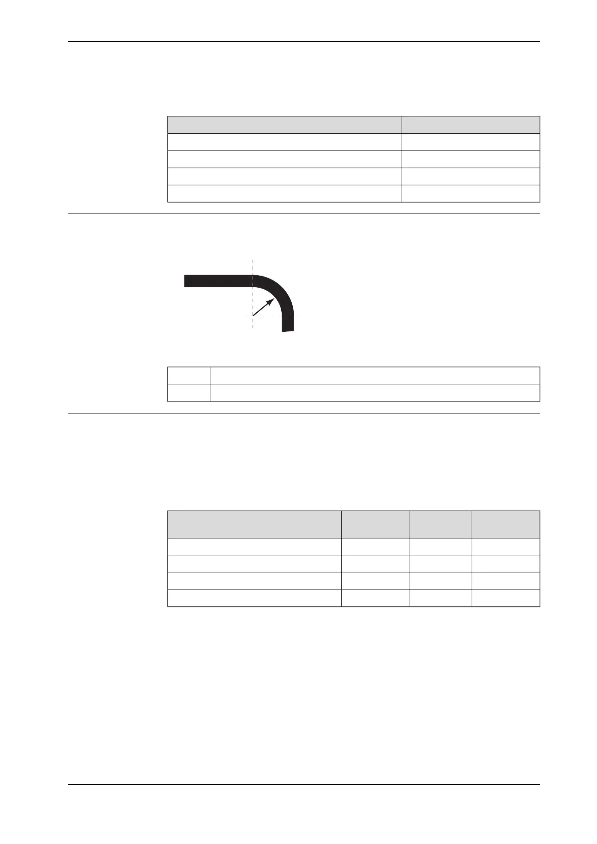
Describes configuring system parameters like Gravity Beta for non-standard mounting angles.
Shows robot cabling and connection points for electrical systems, including connectors on the robot.
Introduces the chapter on recommended maintenance activities, based on a schedule.
Specifies required maintenance activities, intervals, and details where each task is performed.
Details procedures for inspecting various components and labels on the robot.
Covers routine tasks like lubrication, oil changes, and battery replacements.
Details the procedure for changing oil in the robot's wrist unit gearboxes.
Outlines procedures for cleaning the robot based on its protection type and method.
Explains the use of the Service Information System for monitoring robot operating time and maintenance scheduling.
Introduces the chapter on recommended repair activities for the robot and external units.
Covers common procedures applicable to various repair tasks, such as leak-down tests and bearing mounting.
Details how to test gearbox seal integrity after refitting motors or gearboxes.
Provides guidance on mounting and greasing robot bearings, including specific types like tapered bearings.
Explains how to correctly mount different types of seals, including rotating seals, flange seals, and O-rings.
Details how to prepare the robot surface before replacing parts to maintain cleanliness.
Covers procedures for replacing major robot assemblies like cable units and harnesses.
Details the process for removing and replacing the main cable harness for axes 1-3.
Covers procedures related to the robot's upper arm assembly, including wrist replacement.
Details the removal and replacement of the wrist unit for specific IRB 2400 models.
Covers procedures related to the robot's lower arm assembly, including its replacement.
Details the process for removing and replacing the entire lower arm assembly.
Guides on how to remove and replace the tie rod component of the robot.
Covers maintenance and replacement tasks related to the robot's frame and base, like SMB unit replacement.
Details the procedure for removing and replacing the Serial Measurement Board unit.
Explains how to remove and replace the brake release unit located in the robot base.
Covers procedures for removing and replacing individual robot axis motors.
Details the procedure for removing and replacing the motor on axis 1, including gear play adjustment.
Guides on removing and replacing the motor for axis 2, including necessary measurements.
Explains the procedure for removing and replacing the motor on axis 3.
Details replacing motors for axes 4, 5, and 6 on IRB 2400L models.
Covers replacing motors for axes 4, 5, and 6 on IRB 2400/10/16 models.
Covers procedures for removing and replacing robot gearboxes for axes 1-3.
Details the process for removing and replacing the gearbox for axes 1-3.
Explains how to remove and replace the drive shaft unit for axes 5 and 6.
Identifies situations requiring robot system calibration, such as changed resolver values or lost counters.
Describes different calibration types and methods supplied by ABB, including Standard and Absolute Accuracy.
Shows the position of synchronization marks and synchronization positions for each robot axis.
Guides on updating robot axis revolution counters using FlexPendant or TPU.
Details procedures for verifying axis synchronization positions using MoveAbsJ or Jogging.
Provides information on product disposal, hazardous materials, and environmental regulations.
Outlines important safety precautions when disassembling a robot for scrapping.
Introduces general reference information complementing specific procedures in the manual.
Lists relevant industry standards, including EN ISO and European standards, the product conforms to.
Provides a table for converting units used within the manual, such as length, weight, and pressure.
Details procedures for tightening various types of screw joints and applicable torques.
Highlights component weights and recommends lifting accessories for heavy parts.
Lists essential tools included in the standard toolkit for service, maintenance, and installation.
Lists specialized tools required for specific service procedures and calibration.
Informs that spare parts and exploded views are delivered as a separate document via the ABB portal.
States that circuit diagrams are available for registered users on the myABB Business Portal.


