5 Calibration information
5.3. Calibration scale and correct axis position
3HAC022033-001 Revision: K406
© Copyright 2004-2011 ABB. All rights reserved.
5.3. Calibration scale and correct axis position
Introduction
This section specifies the calibration scale positions and/or correct axis position for all robot
models.
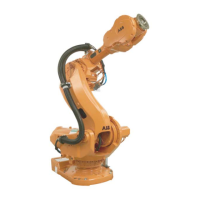
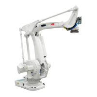
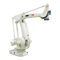
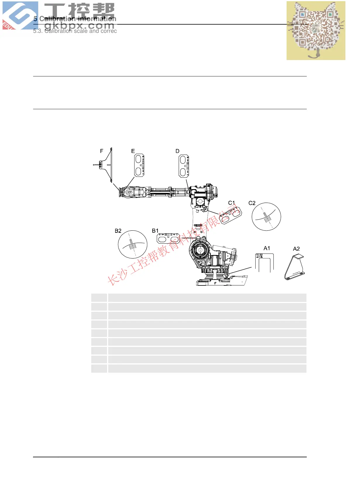
Calibration scales/marks, IRB 7600
The illustration below shows the location of the calibration scales on specific plates and the
calibration marks directly in the casting at axes 2 and 3.
The figure shows IRB 6600, but the scales and their positions are the same.
xx0200000176
Calibration marks at axes 2 and 3
The calibration marks at axes 2, 3 and 6, shown in the figure above, consist of two single
marks that should be positioned opposite to one another when the robot is standing in its
calibration position. One of the marks is more narrow than the other and should be positioned
within the limits of the wider mark.
A1 Calibration scale, axis 1 (early design)
A2 Calibration scale, axis 1 (later design)
B1 Calibration scale, axis 2 (early design)
B2 Calibration mark, axis 2 (later design)
C1 Calibration scale, axis 3 (early design)
C2 Calibration mark, axis 3 (later design)
D Calibration scale, axis 4
E Calibration scale, axis 5
F Calibration scale, axis 6
 Loading...