36 M1M 30 POWER METER USER MANUAL
7.5.Alarms (ALM)
ALARM configuration is used to get info on threshold violations of specific parameters. When the
measurement quantity exceeds the limit, an alarm will be given to prompt users to make corresponding
treatment measures in time.
Each alarm can only be triggered when certain conditions are met. The following graph describes the
process of triggering and releasing an alarm:
Alarm Digital Output
Event
Event
Event
Event
Threshold
Threshold
Variable
Delay
Delay
Hysteresis
Hysteresis
MIN
MAX
When the value of the alarm variable exceeds the threshold and the delay, the alarm will be generated;
and when the alarm variable recovers to the normal range and exceeds the hysteresis and delay, the alarm
will be released. Alarm can be connected to certain DO to control the alarm signal output at the DO. If the
alarm is stored in flash, it can be viewed later in the read data menu. When the device is in alarm state,
ICON will be displayed. If this alarm is selected to be stored in Flash, ICON will also be displayed
Each M1M provides up to 15 alarms; following parameters are available:
Menu Description
NUM Select which alarm will be edited, max 15 alarms can be selected
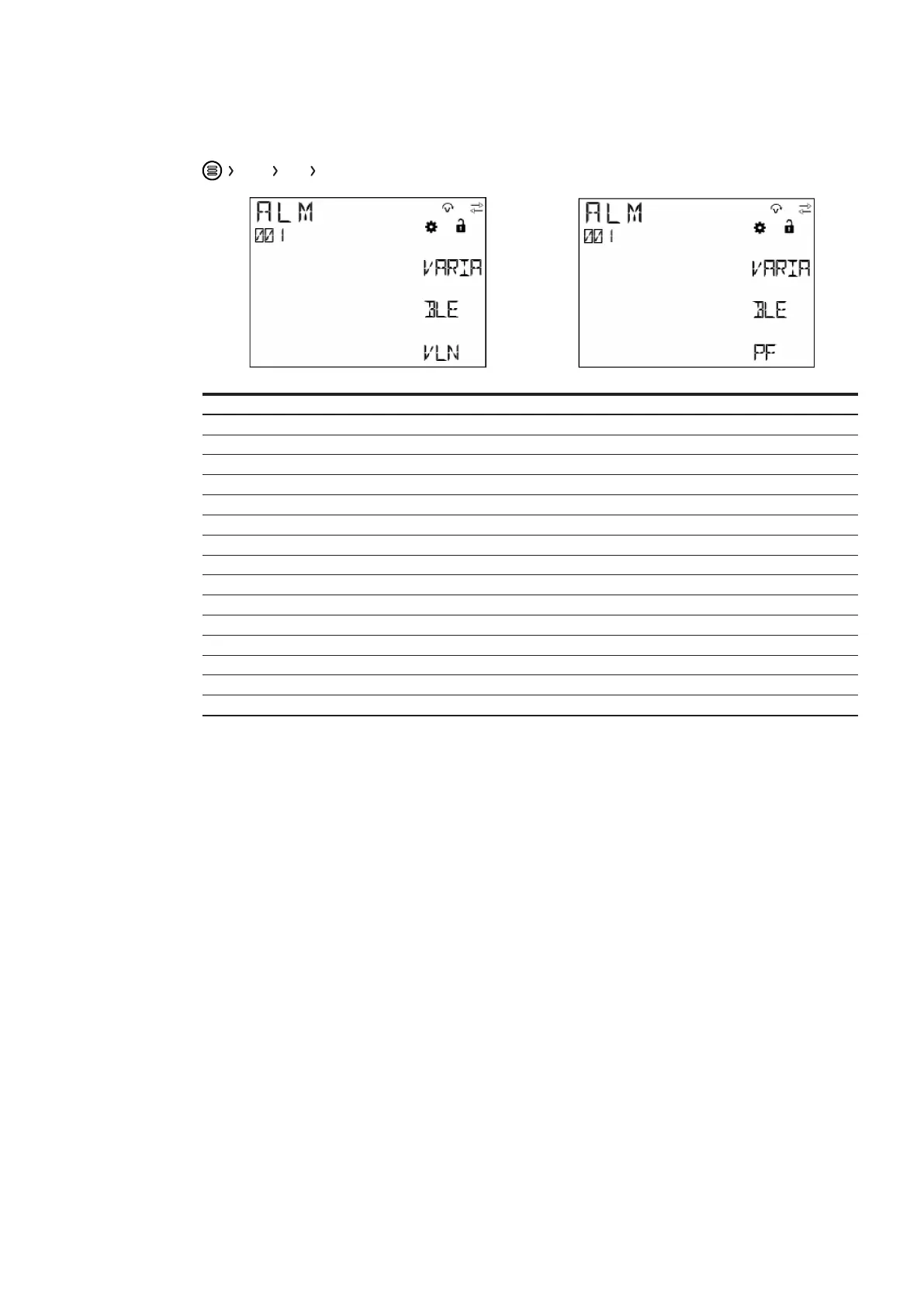
VARIABLE Select alarm variable
PHASE Select the phase of alarm variable
TYPE Type of alarm: cross-up (MAX) or cross-down (MIN)
SETPOINT Set threshold
DELAY Delay time
HYSTERESIS Set hysteresis
LOG Storing the alarm
PORT Select digital output port for alarm
 Loading...