2
2
M
M
N
N
S
S
i
i
S
S
S
S
y
y
s
s
t
t
e
e
m
m
S
S
e
e
t
t
u
u
p
p
2 MNS iS System Setup
2.1 Cubicle identification
For the MNS iS System to operate correctly each
cubicle requires an identification number. One
MLink communicates to a maximum of 7
cubicles. This numbering is defined at the project
engineering stage.
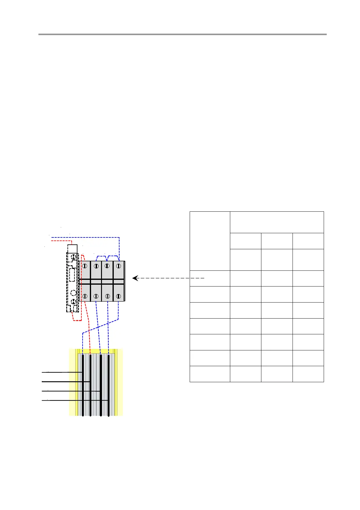
Cubicle numbers are accordingly set by defined
connections of the terminal blocks to the fuse
holder on the top of the 24 V DC Control voltage
supply bar.
MLink identifies the cubicle based on the live
supply bars.
Figure 22 shows exemplarily the coding of
cubi
cle number 1.
0 V
+ 24 VDC
0 V
0 V
Fuse holder
terminal block
Terminal blocks
(A)
B
C
D
E
0 V
+ 24 VDC
Figure 22 Switchboard identification (example)
Connection of the
terminal blocks
B C D
Cubicle
number
(Binary
code 2
0
)
(Binary
code 2
1
)
(Binary
code 2
2
)
1
A E E
2
E A E
3
A A E
4
E E A
5
A E A
6
E A A
7
A A A
Exam
le
2
2
2
2
ABB MNS iS System Setup & Operation Quick Guide / System Release 6.0 – Rev.2 / Aug. 2011

 Loading...