2
2
M
M
N
N
S
S
i
i
S
S
S
S
y
y
s
s
t
t
e
e
m
m
S
S
e
e
t
t
u
u
p
p
2.6 MLink Setup
2.6.1 Gener
al
The communication interface module MLink
collects information from the connected MControl
units.
Maximum units per MLink:
7 cubicles or
60 modules
In case more cubicles/ modules are required,
several MLink units are linked via a Network
Switch.
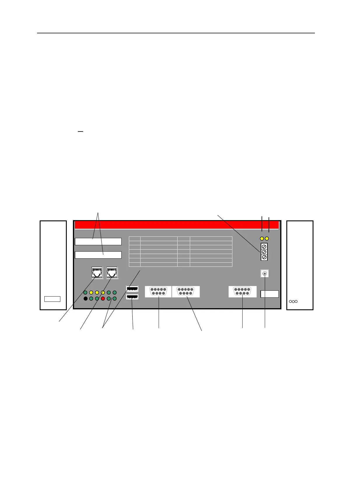
2.6.2 Interfaces and Annunciation
Figure 39 MLink interfaces and annunciation
2.6.3 Compact Flash (CF) Card
The compact flash card contains:
Operating System
IP address
MLink parameters
Fieldbus parameters
The card is inserted to the slot at the left side of
the MLink unit. As soon as the flash card is
inserted and MLink is connected to the voltage
supply, MLink starts polling the MControl units
connected to the switchgear network.
MLink
R 3 5 7 9 11
LAN 1 LAN 2
USB 2
Swg. Bus
12 13
LED Indication
1 Power ON R MLink RESET Button
2 LAN 1 Comm. OK 3 LAN 1 Link OK
4 LAN 2 Comm. OK 5 LAN 2 Link OK
6 DCS Comm. OK 7 MLink FAULT
8 9
10 MLink RUN 11
12 Swg. Bus Receive 13 Swg. Bus Transmit
ABB
USB 1 Serial 1 Serial 2 PROFIBUS
LAN 1 IP Address
LAN 2 IP Address
Slave
Address
MLink
Modbus TCP/
Profinet
LED
Indication
USB
interfaces
(reserved)
Serial
interface
(Redundancy)
Profibus
interface
Internal
switch
ear bus
Device IP Address
LAN1+2
Tx
Rx
Indication
Switchgear Bus
Side view
left
Side view
right
CF card
slot
Power
su
l
Earthing
clam
Ethernet
connection
Modbus RTU
interface
4
4
0
0
ABB MNS iS System Setup & Operation Quick Guide / System Release 6.0 – Rev.2 / Aug. 2011

 Loading...