EasyManua.ls Logo

ABB SACE Emax 2 User Manual

ABB SACE Emax 2
109 pages
To Next Page IconTo Next Page
To Previous Page IconTo Previous Page
Page #48 background imageLoading...
Page #48 background image
ABB | SACE Emax 2
46 | © 2017 ABB | 1SDH000999R0002 - ECN000058721 - Rev. B
Ekip Dip protection trip unit | 5 - List of alarms and signals
5 - List of alarms and signals
LED view
The Ekip Dip trip unit continuously monitors its own operating condition and that of all the devices to which
it is connected. All the signals are available with the front LEDs.
The protection LEDs provide information with various combinations of lighting and flashing, while the power-
on LED, as described on page 35, indicates the power-on conditions of the trip unit.
Figure 68
NOTE: the number of LEDs depends on the version of the trip unit (LI, LSI, LSIG).

Table of Contents

Other manuals for ABB SACE Emax 2

Question and Answer IconNeed help?

Do you have a question about the ABB SACE Emax 2 and is the answer not in the manual?

ABB SACE Emax 2 Specifications

General IconGeneral
TypeAir circuit breaker
Rated Current800 A to 6300 A
Breaking CapacityUp to 150 kA at 415 V AC
Frequency50/60 Hz
Number of Poles3, 4
InstallationFixed or withdrawable
StandardsIEC 60947-2
Trip UnitEkip Touch, Ekip Hi-Touch
CommunicationModbus, Profibus, Ethernet
Rated Voltage690 V AC

Summary

Transport and Checking on Receipt

Description

Circuit-breaker Overview

Details of circuit-breaker types, structure, and components.

Environmental Conditions

Installation Environment

Requirements for dry, dust-free installation locations, and environmental factors.

Installation

Warnings and Precautions

Safety guidelines before starting installation procedures.

Ekip Protection Trip Units

Introduction and Trip Unit Overview

General introduction to Ekip trip units, types, and functions.

Ekip Dip Interface and Protections

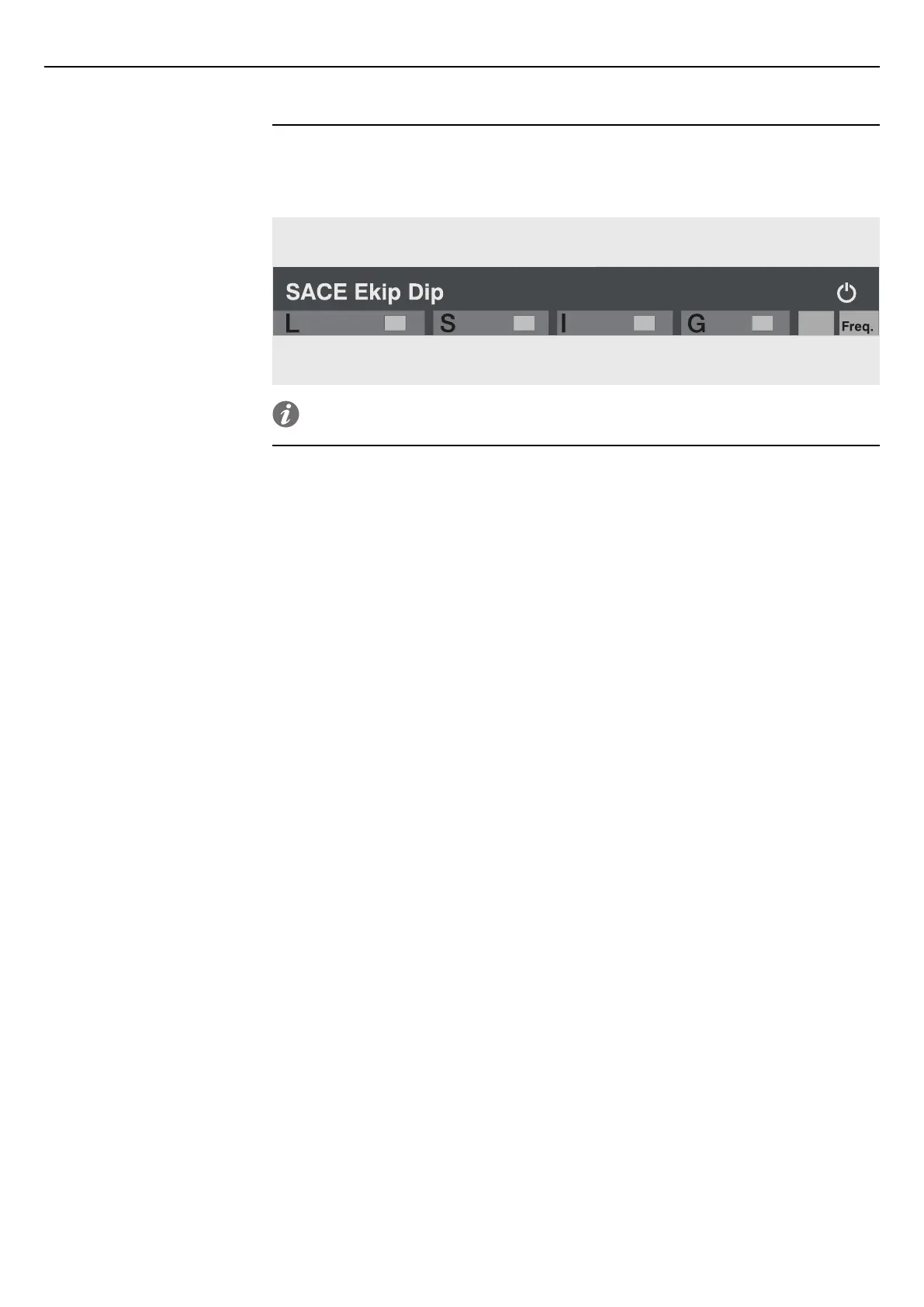
Details of the Ekip Dip interface, operator controls, and protection functions.

Accessories

Putting into Service and Maintenance

Putting into Service

General checks and procedures for initial setup and commissioning.

Alarms and Failures

Identifying and resolving faults, causes, and error signals.

Maintenance Operations

Procedures for inspection, cleaning, lubrication, and testing.

Related product manuals