ABB | SACE Emax 2
Accessories | 2 - Circuit diagrams
57 | © 2017 ABB | 1SDH000999R0002 - ECN000058721 - Rev. B
Continued from the previous page
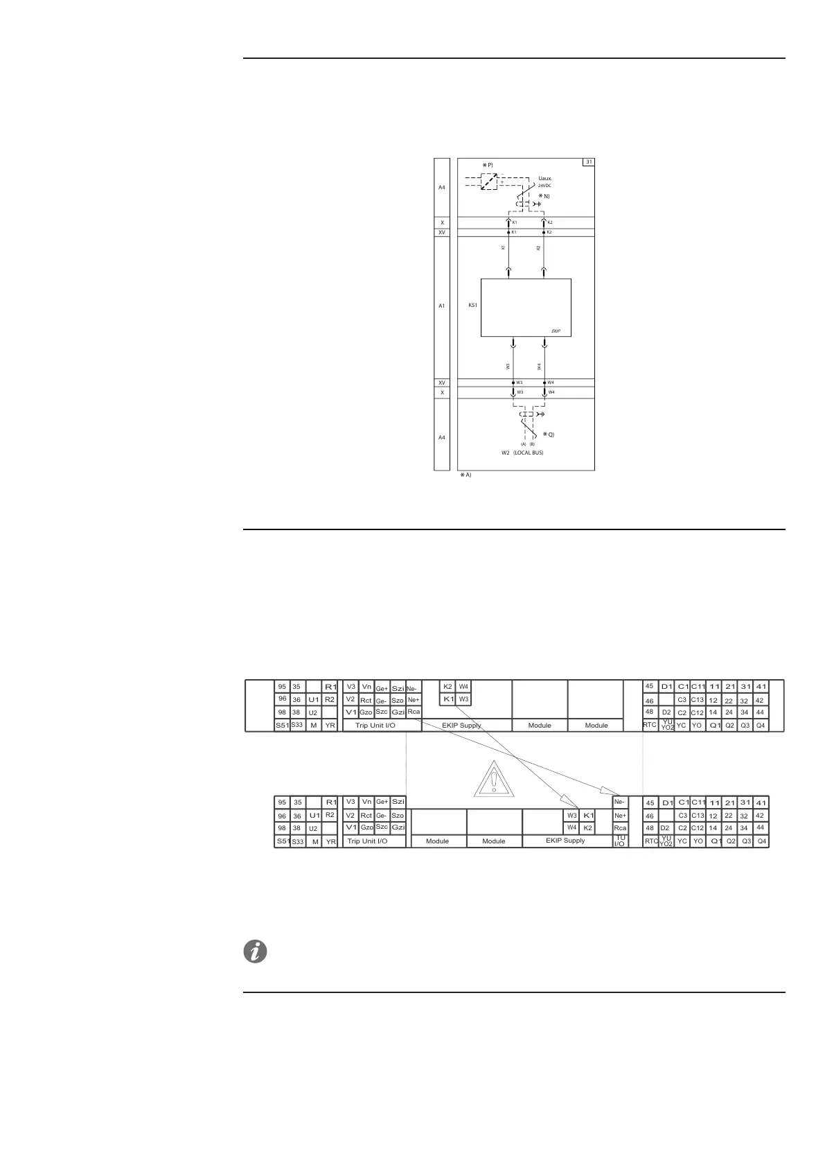
The wiring diagram of the circuit breaker is illustrated without any indication of the auxiliary power supply of
the Ekip trip unit. If the circuit-breaker is equipped with the Ekip Supply module, for information see the page
62.
If the circuit-breaker is not equipped with the Ekip Supply module, for the connection of the auxiliary power
supply of the Ekip trip unit see the direct power supply diagram shown below:
X
A4
XV
Uaux.
K51
A1
XV
X
K1
K1
K1
K2
K2
K2
24VDC
A4
+
W3
W3 W4
(B)(A)
(LOCAL BUS)
W3 W4
W4
*
P)
W2
*
N)
Diagram 31 - Direct auxiliary power supply
Circuit-breaker terminal box
The circuit-breaker is equipped with a terminal box for the wiring of the accessories that varies according to
the type of circuit-breaker:
• Terminal box for circuit-breaker in fixed version.
• Terminal box for circuit-breaker in withdrawable version.
The differences between the two terminal boxes are shown in Figure 72 :
C13
C3
Ne+
Rca
Ne-
K2
K1
W3
W4
Trip Unit I/O
V3
Vn
Ge+
Szi
Szo
Ge-
Rct
V2
V1
Gzo
Szc
Gzi
S51
95
96
98
38
36
35
M
U1
U2
R1
R2
YR
EKIP Supply
S33
Q4
44
42
4131
32
34
Q3Q2
24
22
21
11
12
14
Q1
C11
C12
YO
YC
C2
C1
D1
D2
YU
RTC
48
46
45
Module Module
YO2
95
35
U1
96
36
U2
R1
98
38
R2
V3
Vn
Ge+
Szi
V2
Rct
Ge-
Szo
V1
Gzo
Szc
Gzi
W3
K1
W4
K2
Ne-
Ne+
Rca
45
D1
C1
C11
11
21
31
41
46
C3
C13
12
22
32
42
48
D2
C2
C12
14
24
34
44
S51
S33
M
YR
Trip Unit I/O
RTC
YC
YO
Q1
Q2
Q3
Q4
TU
I/O
YU
YO2
Module
Module
EKIP Supply
Figure 72
On page 58, the representation of the terminal box for a circuit-breaker in fixed version is shown.
NOTE: for the details of the wiring diagram of each individual accessory, please refer to the
specific pages that describe the accessory in question.
Continued on the next page
 Loading...