ABB | SACE Emax 2
Accessories | 2 - Circuit diagrams
61 | © 2017 ABB | 1SDH000999R0002 - ECN000058721 - Rev. B
Continued from the previous page
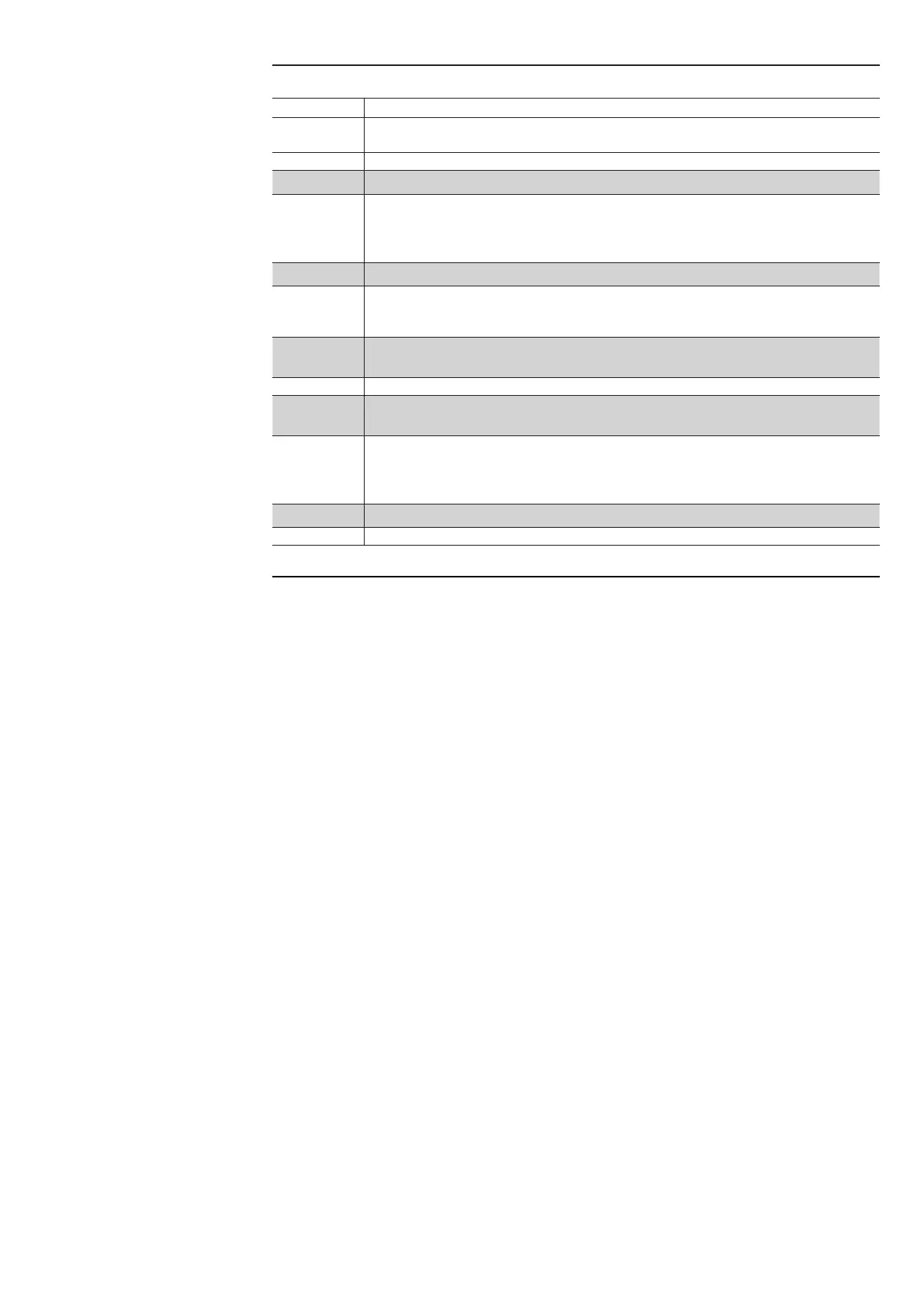
The following is a key to the notes used in the wiring diagrams:
Note Description
A)
For the zone selectivity and local bus function is required the presence of an auxiliary
power supply.
C) Always supplied with Ekip Com module.
D) Always supplied with motor for loading the closing springs (diagram 13)
H)
Make the connection using the ABB cable supplied. There must be no break in the cable.
Use of other cables or extensions using intermediate terminal boxes is not allowed. With
a three-pole circuit-breaker, poles Ne+ and Ne- of connector X (or XV) are short-circuited
(unless the external neutral is present): realize short-circuit connection if absent.
I) Obligatory in the case of presence of any Ekip module.
L)
In the presence of diagram 32, up to three applications can be provided between
diagrams 41… 58 taken only once. In addition, it is possible to duplicate an Ekip Com
module that may be selected choosing between diagrams 61...66.
M)
The opening and closing commands from module Ekip Actuator are available with YO
and YC coils maximum voltage of 110 - 120 V DC and 240 - 250 V AC.
N) Use cable type Belden 3105A or equivalent.
O)
In the presence of several Ekip Com modules with withdrawable version circuit-breakers,
the contact S75I/5 should be connected only once to a single module.
P)
The auxiliary voltage Uaux enables activation of all the functions of the EKIP electronic
protection trip units. Since a ground insulated Uaux was request, is necessary to use
“galvanically separated convertors” which comply with the standard IEC 60950 (UL 1950)
or equivalent
Q) Use cables type Belden 3105A or equivalent, with maximum length 15 m.
R) Suggested RJ45 cable: CAT6 STP
 Loading...