A
Amanda JohnsonAug 14, 2025
What to do if Acer AO756 Laptop power on issues?
- AAlice Daniel PhDAug 14, 2025
If your Acer Laptop is not turning on, please refer to Figure 4:1. Power On Issues on page 4-3 for troubleshooting steps.
 Loading...
What to do if Acer AO756 Laptop power on issues?
If your Acer Laptop is not turning on, please refer to Figure 4:1. Power On Issues on page 4-3 for troubleshooting steps.
What to do if internal keyboard failure on Acer AO756 Laptop?
If the internal keyboard on your Acer Laptop is not working, please see Figure 4:4. Internal Keyboard Failure on page 4-7 for troubleshooting steps.
What to do if touchpad failure on Acer AO756?
If the touchpad on your Acer Laptop isn't functioning, refer to Figure 4:5. Touchpad Failure on page 4-8 for troubleshooting tips.
| Display | 11.6" HD (1366 x 768) LED-backlit |
|---|---|
| RAM | Up to 4GB DDR3 |
| Storage | 320GB / 500GB HDD |
| Graphics | Intel HD Graphics |
| Operating System | Windows 7 Home Premium / Windows 8 |
| Wireless | 802.11b/g/n |
| LAN | 10/100 Mbps Ethernet |
| Processor | Intel Celeron 847 / 877 |
| Battery | 4-cell Li-ion |
| Weight | 1.38 kg |
| Dimensions | 285 x 202 mm |
| Ports | 2 x USB 2.0, HDMI, VGA, Headphone/Microphone combo jack |
| Card Reader | Multi-in-1 card reader |
Includes revision history, copyright notice, and disclaimer.
Explains warning symbols and typographical conventions used in the manual.
Provides details on ordering FRU parts and services from Acer.
Details features, operating system, platform, memory, and display.
Covers privacy, storage, graphics, and audio subsystems.
Lists communication features, dimensions, weight, and power details.
Details I/O ports, keys, environment specs, and warranty information.
Illustrates top, front, left, right, and base views of the notebook.
Explains touchpad basics, usage, keyboard functions, and hotkeys.
Covers block diagrams, detailed specifications, and component lists.
Guide to accessing and navigating the BIOS setup utility.
Details on Information, Main, Security, Boot, and Exit BIOS tabs.
Procedures for setting, changing, and removing BIOS passwords.
Instructions for updating system BIOS using DOS or WinFlash utilities.
Information on using DMI tools for system management.
Steps for unlocking HDD password and clearing BIOS passwords.
Procedure for creating and using a USB flash crisis disk for recovery.
Diagrams showing locations of jumpers and connectors on mainboard and daughterboards.
Identifies connectors on the top side of the mainboard.
Identifies connectors on the bottom side of the mainboard.
Shows connector and LED locations on the LED board.
Illustrates connectors on the IO board.
Shows connector locations on the HDD board.
Locates the Clear CMOS jumper on the mainboard.
Provides general procedures for diagnosing and resolving issues.
Troubleshooting steps for systems that do not power on.
Steps to diagnose and resolve no display or POST problems.
Guidance for diagnosing and fixing abnormal video output.
Troubleshooting steps for specific component failures.
Troubleshooting for BIOS problems and intermittent system issues.
Introduction, recommended tools, and maintenance flowcharts.
Procedures for removing/installing battery, dummy card, and base door.
Detailed steps for servicing HDD, Fan, DIMM, WLAN, Case, Mainboard, etc.
Procedures for LCD module, bezel, panel, brackets, camera, and microphone.
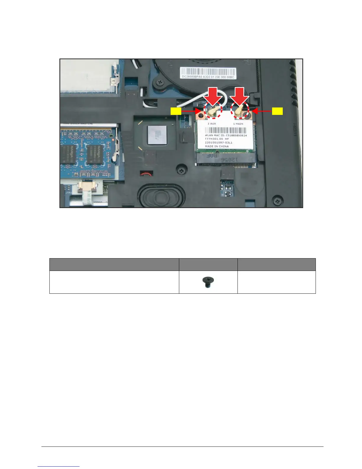
Steps for servicing DC-In cable and WLAN antennas.
Introduction to FRU listing, ordering parts, and disposal guidelines.
Diagrams and part numbers for main, lower, upper case, LCD, and HDD assemblies.
Lists FRUs for boards, cables, cases, touchpads, keyboards, and chipsets.
Catalog of screws with types and part numbers for assembly.
Lists components verified for compatibility with Windows 7.
Details compatibility testing performed in Windows 7 environment.
Lists compatible adapters, CPUs, HDDs, keyboards, and memory.
Information on online technical support services and resources.