Machine Maintenance Procedures 3-37
5. Remove module from lower cover.
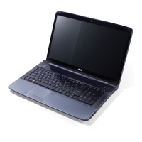
6. Remove tape (F) securing RJ45 cable (C) to module connector (G). (Figure 3-46)
Figure 3-46. Removing RJ45 Cable (1 of 2)
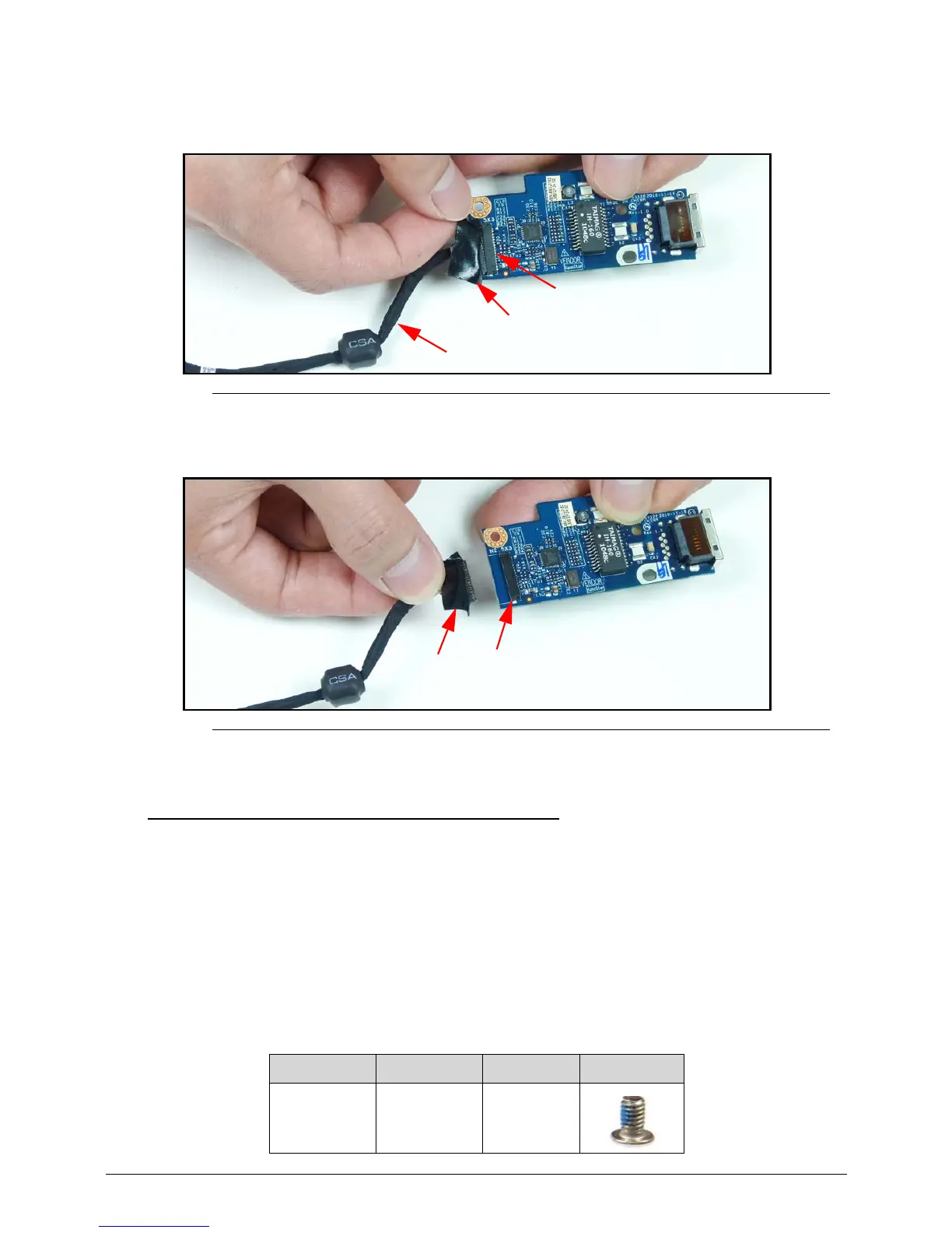
7. Disconnect cable (C) from module connector (G). (Figure 3-47)
Figure 3-47. Removing RJ45 Cable (2 of 2)
RJ45 Module Installation 0
1. Connect cable (C) to module connector (G). (Figure 3-47)
2. Install tape (F) securing RJ45 cable (C) to module connector (G). (Figure 3-46)
3. Install module on lower cover. (Figure 3-45)
4. Install and secure screw (E) to module.
5. Connect RJ45 cable (C) (disconnected) to mainboard connector (D). (Figure 3-44)
6. Install tape (B) securing RJ45 cable to mainboard connector.
7. Install upper cover.
ID Size Quantity Screw Type
E M2.5x3.0 Ni 1
 Loading...