40
IVEDITI 1707 - 4880981_01
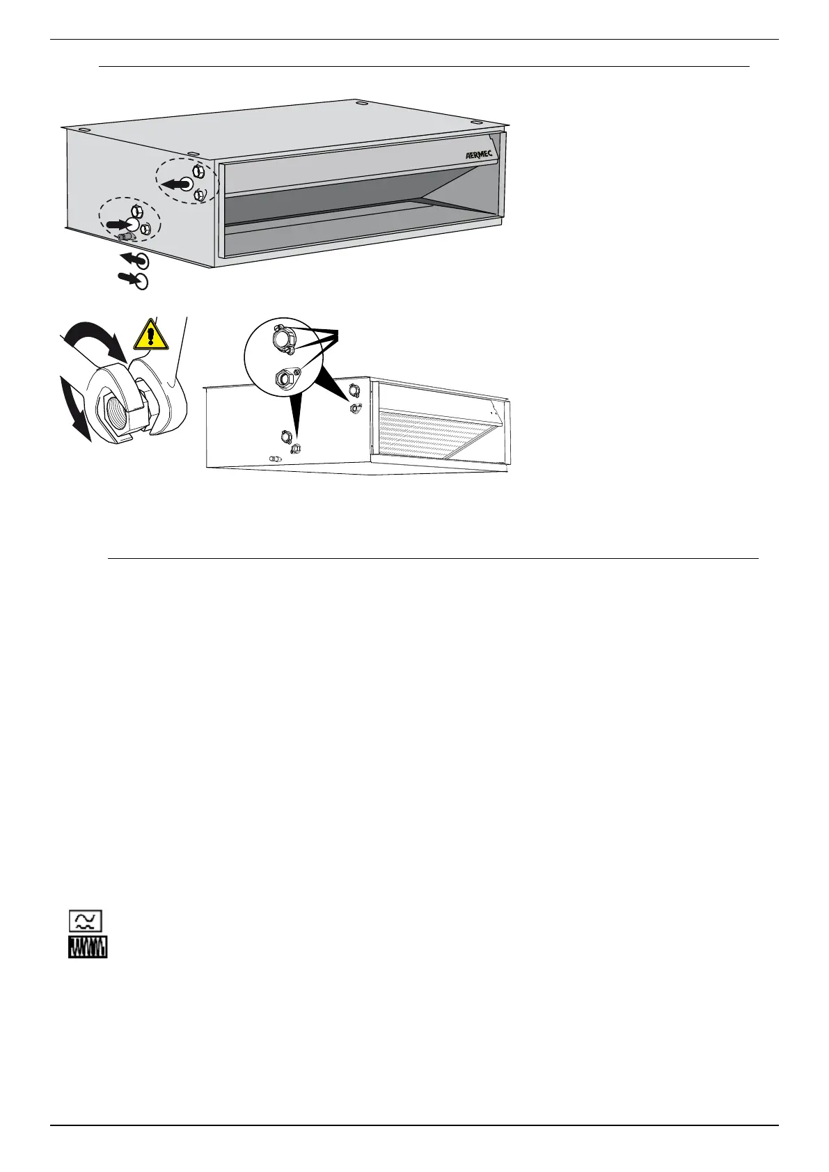
- Make the hydraulic connections.
ATTENTION: Always use a wrench and
counter-wrench to fix the pipes.
The position, type and diameter of the
hydraulic connections are specified in the
dimensional data.
It is recommended to insulate water
pipelines and/or to install the suitable
auxiliary condensate collection tray, available
as an accessory, in order to avoid dripping
during cooling operation.
During installation check the seal of the
connections.
Attention: Discharge the hydraulic system
The vent valves are positioned on the top of
the coil close to the hydraulic fittings.
Attention: to drain the unit, use the
discharge valves placed at the bottom of the
coil close to the hydraulic fittings.
B
A
IN
OUT
A
B
Air vent valves
and water drain from coil
The fan coil may be permanently damaged if a
different electric power supply is used.
1000 hz
The following measures must be considered for
installations with three-phase power supply:
1. In the presence of 3P + N isolators or magnet
circuit breakers, the release current must be at
least 170% of the value absorbed by the overall
load of the fan coils for each phase.
2. The neutral wire section must be sized
considering a working current equal to 170% of
the value absorbed by the overall load of the fan
coils for each phase.
SPECIFICATIONS OF THE CONNECTION CABLES
300/500 V insulation enclosed inside a pipe or
trough.
mm2.
All the cables must be enclosed inside a pipe or
trough until they are inside the fan coil.
The cables at the outlet of the pipe or cable
trough must be positioned in a way not to
undergo traction or twisting stress and be
however, protected from external agents.
The unit must be combined with a control
device to be purchased separately.
Refer to the wiring diagram and instructions in
this manual before making the connections.
The control panel can be fitted on a metal wall,
unless it is permanently connected to the earth
plug.
Carefully read the instructions and, if necessary,
carry out the configuration as indicated, before
installing the control device. Some control
devices must be combined with components
supplied as accessories, verify their availability.
ATTENTION: Verify that the control device is
compatible with the electrical features of the
fan coil.
In combining the control devices, follow the
relative wiring diagram and the instructions in
this manual.
If present, connect the valve and the probe
to the terminal board according to the
positions specified in the wiring diagram. In
installations with three-way valve, the minimum
temperature probe of the water must be
moved from its seat in the coil, to the flow pipe
upstream of the valve.
Follow the wiring diagram.
ATTENTION: verify whether the installation
has been carried out correctly. Follow the
verification procedures indicated in the manuals
of the control devices.
ATTENTION: Then run an operating test.
ELECTRIC CONNECTIONS
 Loading...