120 34980A Service Guide
5 Disassembly and Repair
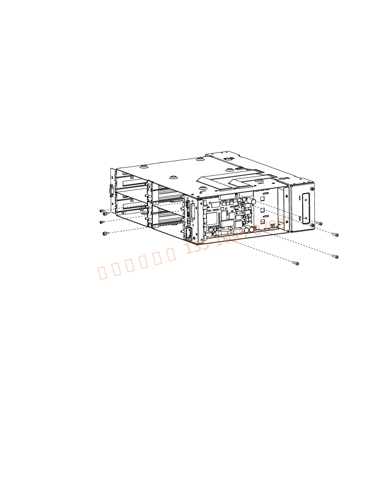
KOM Removal
1 Remove the power supply (see the procedure on page 118).
2 Disconnect the two ribbon cables on the top of the chassis.
3 Use a 3/16” nut driver to remove the nuts holding the Ext Trig DB9 connector on the
rear panel. Use a 9/32” nut driver to remove the nuts holding the GP-IB connector on
the rear panel.
4 Use a T20 Torx to remove the four screws holding the KOM printed circuit assembly
to the mainframe. Lift out the assembly.

 Loading...


