54 34980A Service Guide
3 Calibration Procedures
Internal DMM
Input Connections
Test connections to the internal DMM are best accomplished using the rear panel Analog
Bus connector (ABus). You may need to remove the cover for access to this connector. A
test fixture can be constructed using a standard DB9 male connector, some shielded
twisted pair PTFE
insulated cables, and appropriate connectors for the calibrator output
you are using.
You may also use one of the multiplexer modules to connect the calibrator output to the
DMM. If you use a multiplexer module, you must take into account any additional relay
contacts and resistances in the measurement path. To do this, use the switch/measure
model to set up the DMM and switches, not the scan model. For example, send:
conf:fres 100;:rout:clos (@1001,1021,1911,1922)
read? (should return something close to zero)
cal:val 0
cal?
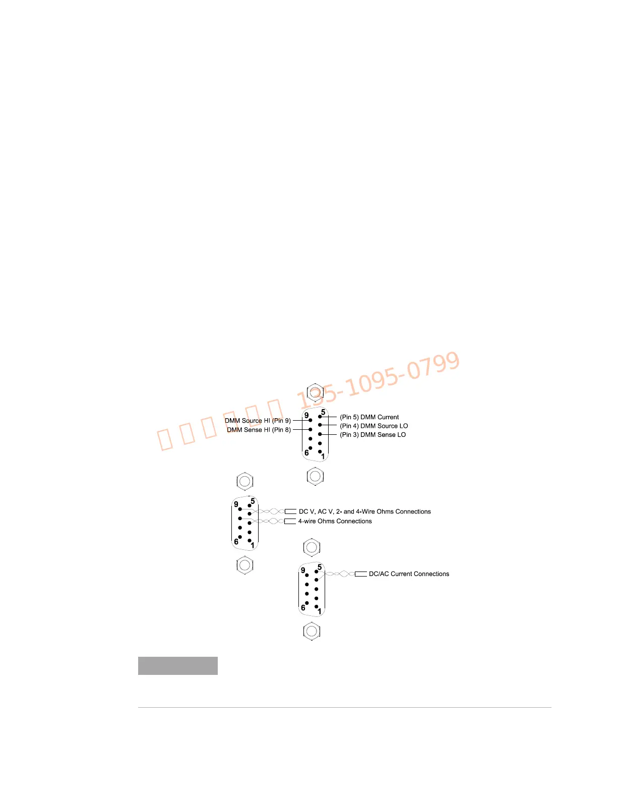
In this manual, the direct ABus connection is the one described. Connections for the
ABus connector are shown below.
Use shielded twisted pair PTFE insulated cables to reduce settling and
noise errors. Connect the shield to the source LO output.
PTFE is a registered trademark of E.I. du Pont de Nemours and Company.

 Loading...


