60 U1241B/U1242B User’s and Service Guide
6 Specifications and Characteristics
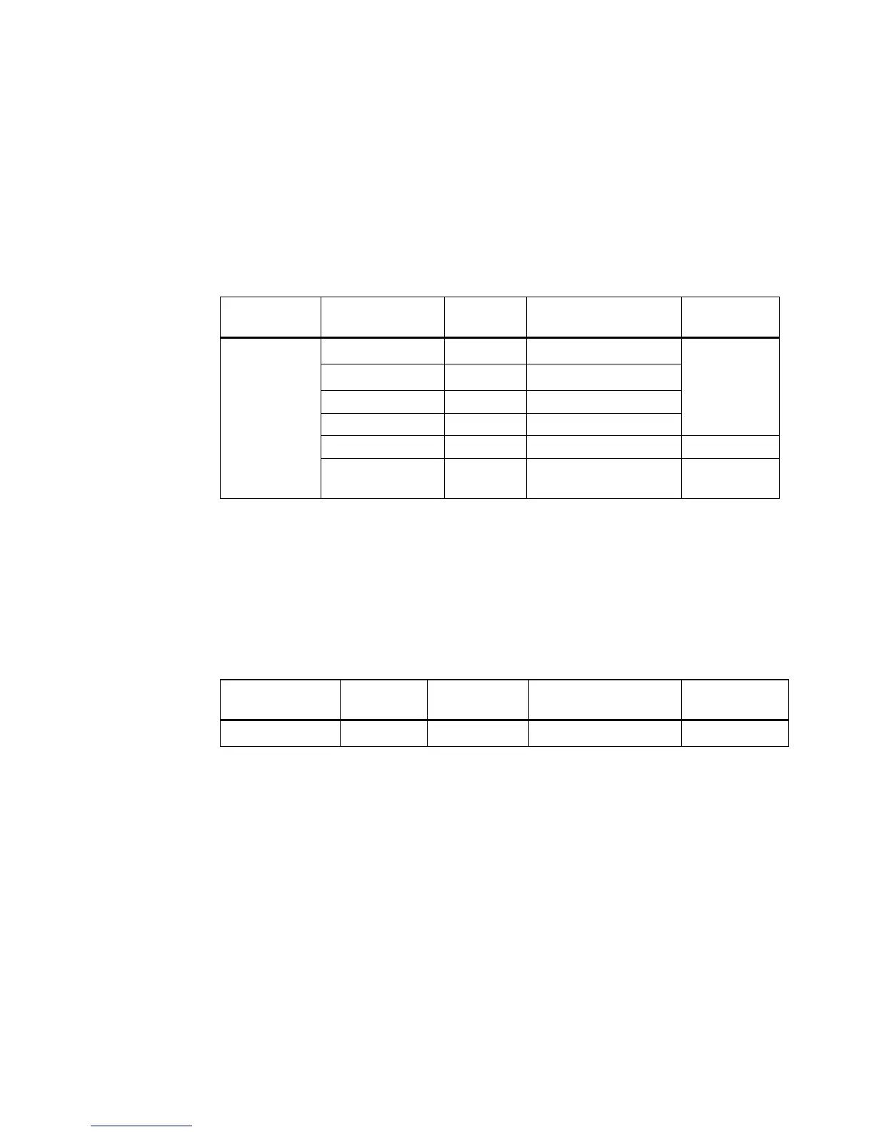
Resistance Specifications
Table 6 -8 Resistance specifications with accuracy of ± (% of reading + No. of Least
Significant Digit)
Diode Check/Audible Continuity Test Specifications
Table 6 -9 Diode test/audible continuity test specifications with accuracy of ± (% of
reading + No. of Least Significant Digit)
[1] The maximum open voltage is < 2.8 V. For instant continuity, the built-in buzzer sounds when
resistance is <10% of each resistance range.
[2] The accuracy of 1 kΩ and 10 kΩ is specified after Null function, which is used to substrate the test
lead resistance and the thermal effect.
[3] For the range of 100 MΩ, the R.H. is specified for < 60%. The temperature coefficient will be 0.15
times of specified accuracy as > 50 MW..
[4] Overload protection: 1000 V R.M.S. for circuits < 0.3 A short circuit current. The built-in buzzer
sounds when reading is approximately below 50 mV and audible single tone for normal forward
Function
Range Resolution
Test Current/
Burden Voltage
Accuracy
Resistance
[1]
1000.0 Ω
[2]
0.1 Ω 0.5 mA
0.3% + 3
10.000 kΩ
[2]
0.001 kΩ 50 μA
100.00 kΩ 0.01 kΩ 4.91 μA
1000.0 kΩ 0.1 kΩ 447 nA
10.000 MΩ 0.001 MΩ 112 nA 0.8% + 3
100.00 MΩ
[3]
0.01 MΩ
112 nA
(in parallel with 10 MΩ)
1.5% + 3
Function Range Resolution Test Current/
Burden Voltage
Accuracy
Diode test
[4]
1 V 0.001 V Approximately 0.5 mA
0.3% + 2