Rockwell Automation Publication 1734-UM001E-EN-P - July 2013
102 POINT I/O Module Data
Analog Input Modules
The 1734-IE2C Analog Input Module is a two-channel module that converts an
analog input current to a digital value. The module resolution is 16 bits across 0
to 21 mA. The module has two modes.
• 0…20 mA
• 4…20 mA (default mode)
• Scaling to any 16-bit signed integer (–32,768…+32,767) -
Default for 1734-IE2C scalers are +3277 @ 4 mA for low
and +16,383 @ 20 mA for high
• Operates in Unipolar mode
The 1734-IE2V Analog Input Module is a two-channel module that converts an
analog input voltage to a digital value. The module resolution is 16 bits across -
10…+10V. The module has two modes.
• 0…10V DC (default mode)
• +/- 10V dc
• Scaling to any 16-bit signed integer (–32,768…+32,767) -
Default for 1734-IE2V scalers are 0 @ 0V for low
and +10,000 @ 100V for high
• Operates in Unipolar or Bipolar modes
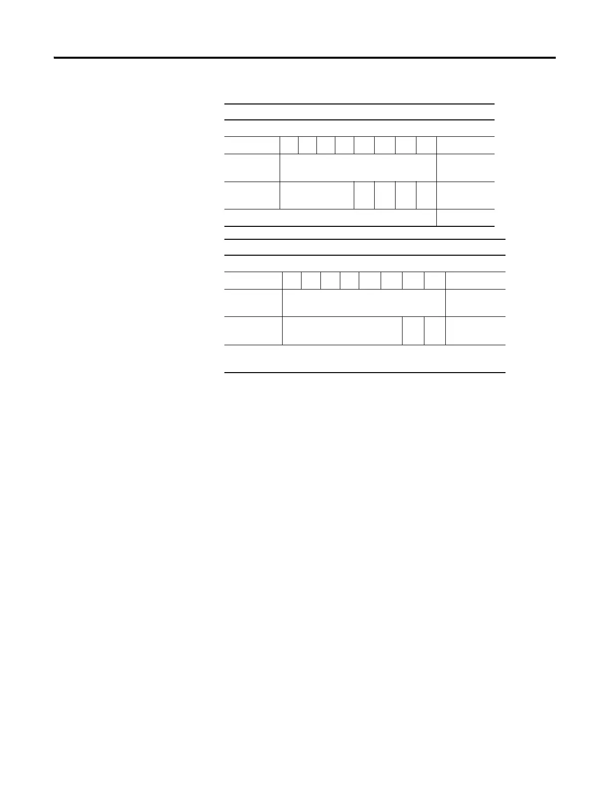
Default Data Map for the 1734-OW4 Output Module
Message Size: 1 Byte
76543210
Produces
(scanner Rx)
No produced data
Consumes
(scanner Tx)
Not used Ch
3
Ch
2
Ch
1
Ch
0
Channel state
Where: 0 = off, 1 = on
Default Data Map for the 1734-OX2 Relay Output Module
Message Size: 1 Byte
76543 2 1 0
Produces
(scanner Rx)
No produced data
Consumes
(scanner Tx)
Not used Ch
1
Ch
0
Channel state
Where: 0 = NO contact off, NC contact on
1 = NO contact on, NC contact off

 Loading...


