Rockwell Automation Publication 1734-UM001E-EN-P - July 2013
98 POINT I/O Module Data
These POINT I/O modules produce one byte of input data (scanner Rx). They
do not consume I/O data (scanner Tx).
Digital Output Modules
Read this section for information about digital output modules.
Digital DC Output Modules
The features of DC output modules include the following:
• 24V DC outputs with a range of 10…28.8V dc
• Output diagnostic features are incorporated to assist in troubleshooting
• Current limited outputs of up to 2 A with respect to their DC return
• Autobaud (will match baud of existing devices on the network)
• Sequential auto addressing
I/O messages are sent to (consumed) and received from (produced) these
POINT I/O modules. These messages are mapped into the processor memory.
(1)
These POINT I/O modules produce one byte of input data (scanner Rx). They
consume one byte of output data (Scanner Tx).
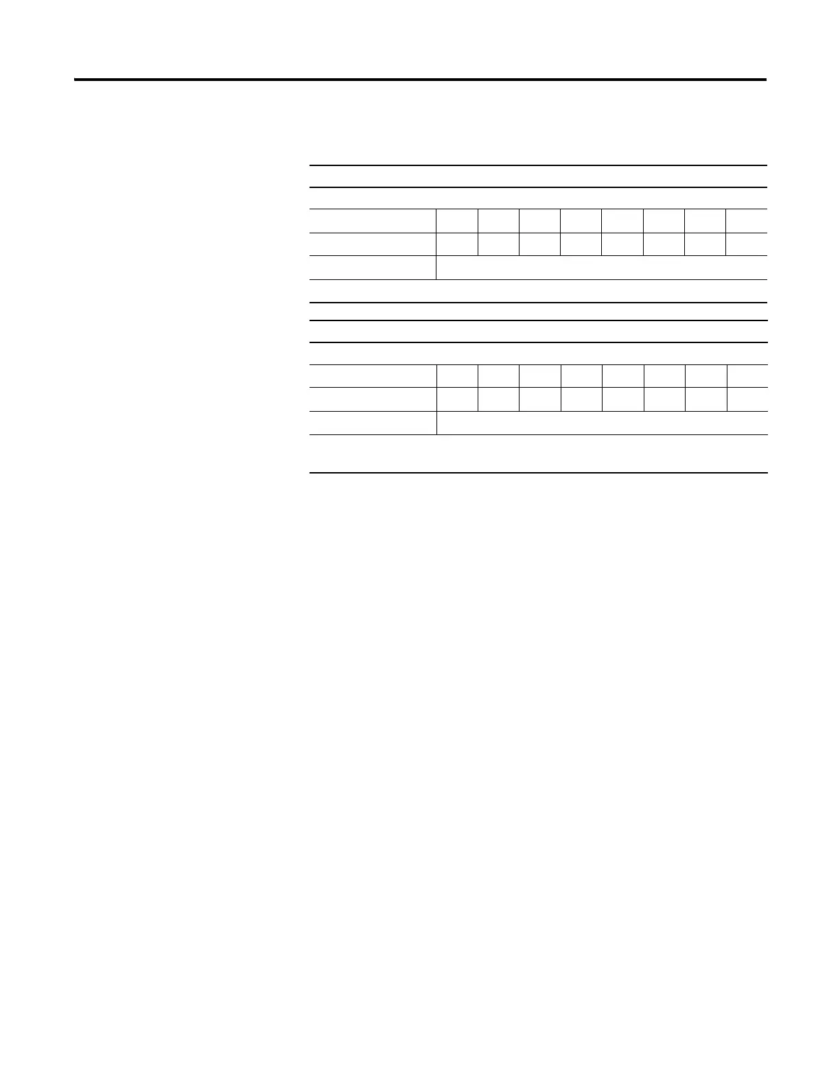
Default Data Map for the 1734-IA2 and 1734-IM2 Input Modules
Message Size: 1 Byte
76543210
Produces (scanner Rx) Ch1 Ch0
Consumes (scanner Tx) No consumed data
Where: Ch0 = channel 0, Ch1 = channel 1; 0 = off, 1 = on
Default Data Map for the 1734-IA4 and 1734-IM4 Input Modules
Message Size: 1 Byte
76543210
Produces (scanner Rx) Ch3 Ch2 Ch1 Ch0
Consumes (scanner Tx) No consumed data
Where: Ch0 = channel 0, Ch1 = channel 1; Ch2 = channel 2, Ch3 = channel 3,
0 = off, 1 = on

 Loading...


