Rockwell Automation Publication 1734-UM001E-EN-P - July 2013
Calibrate Your Analog Modules 121
Calibrate the Analog
Current Input Module
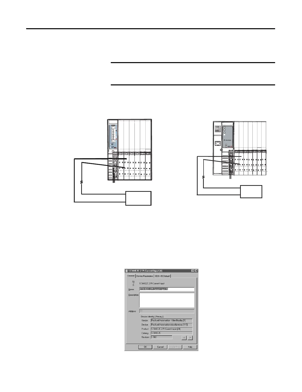
To calibrate your current input module, connect the module in a system similar
to that shown in the figure.
1. Double-click the icon to bring up the General parameter dialog.
Apply power to the power supply and module for at least
10 minutes before calibrating the module. This allows
internal temperatures to stabilize, and reduces drift errors.
PDN IE2C
250 Ω
Current Source
DeviceNet Input
Power Supply Voltage
Channel 0
Connect to 0 and 4
Channel 1
Connect to 1 and 5
250 Ω resistor
protects the current
source in the event
of shorted wires.
01 01 01 0101
01
01
Module
Status
Network Activity
Status
Network
Status
1734-AENT
PointBus
Status
Field
Power
System
Power
02
0
AENT IE2C
EtherNet/IP Input
44037
Current Source
Power Supply Voltage
250 Ω
Channel 0
Connect to 0 and 4
Channel 1
Connect to 1 and 5
250 Ω resistor
protects the current
source in the event
of shorted wires.
44035

 Loading...


