Rockwell Automation Publication 1734-UM001E-EN-P - July 2013
Install POINT I/O Modules 43
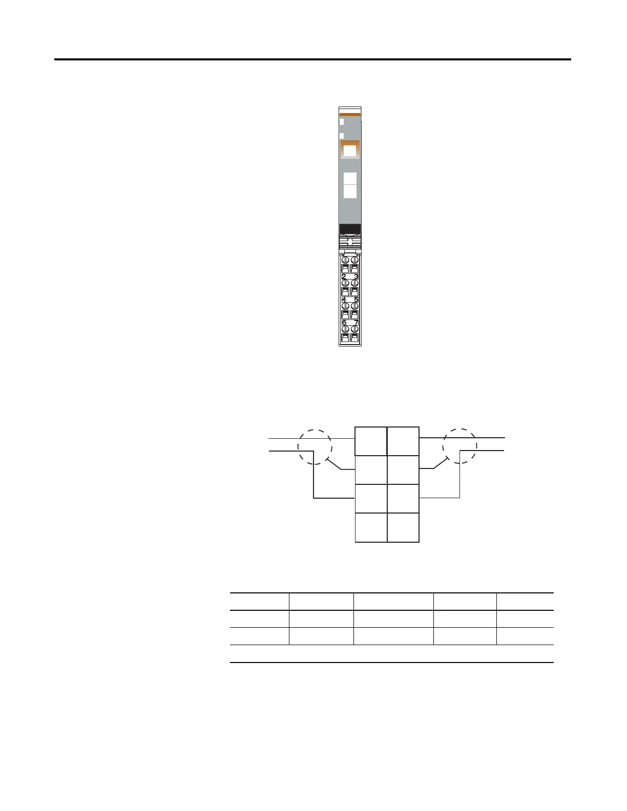
1734-IE2V Analog Voltage Input Module
1734-IE2V Analog Voltage Input Module Wiring Diagram
Channel Voltage Input Chassis Ground Common Supply
00 2 4 6
11 3 5 7
12/24V DC is provided by the internal power bus.
41974
Module Status
Network Status
Status of Input 0
Status of Input 1
Input 0 Connection
Chas Gnd
C
Input 1 Connection
Chas Gnd
C
Chas Gnd = Chassis ground
C = Common
V = Supply
Analog
Voltage
Input
Module
Status
Network
Status
1734
IE2V
NODE:
0
1
In 0 In 1
C
C
VV
Voltage
Input
In = Input channel
Chas Gnd = Chassis Ground
C = Common
V = 12/24V DC supply
3
5
7
0
1
2
4
6
Voltage
Input
Chas
Gnd
Chas
Gnd

 Loading...


