Rockwell Automation Publication 1734-UM001E-EN-P - July 2013
Install POINT I/O Modules 9
Install the Mounting Base
Assembly
The 1734-TB, 1734-TBS, 1734-TB3, or 1734-TB3S wiring base assembly
consists of a 1734-MB mounting base and a 1734-RTB or 1734-RTBS removable
terminal block.
An alternative is the 1734-TOP, 1734-TOPS, 1734-TOP3, or 1734-TOP3S
POINT I/O one-piece terminal base.
Refer to the figures that show these wiring bases.
To install the mounting base assembly on the DIN rail, proceed as follows.
24VDC
Source
Output
Module
Status
Network
Status
1734
OB4E
NO
DE:
0
1
2
3
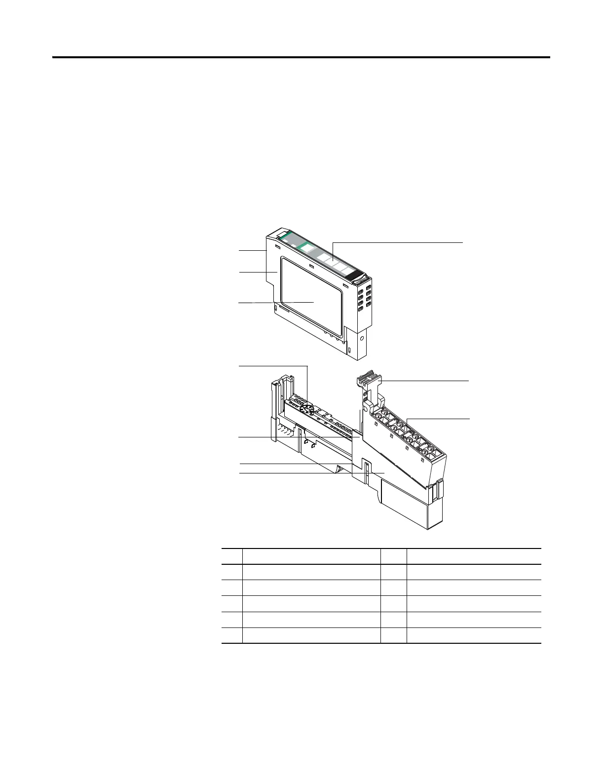
Description Description
1 Module Locking Mechanism 2 Slide-in Writable Label
3 RTB Removing Handle 4 Removable Terminal Block (RTB)
5 Mounting Base 6 Interlocking Side Pieces
7 DIN Rail Locking Screw (orange) 8 Mechanical Keying (orange)
9 Module Wiring Diagram 10 Insertable I/O Module

 Loading...


