Rockwell Automation Publication 1734-UM001E-EN-P - July 2013
10 Install POINT I/O Modules
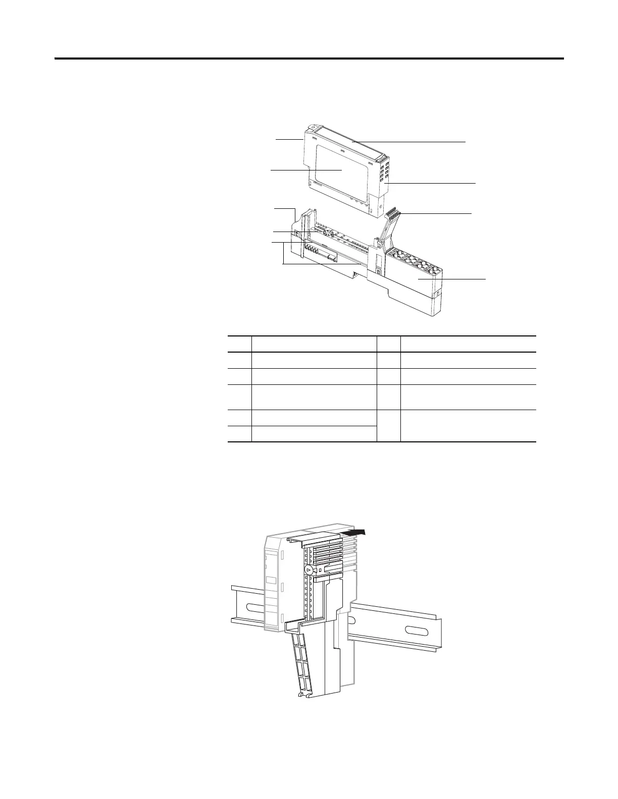
1. Position the mounting base (wiring base assembly) vertically above the
installed units (adapter, power supply, or existing module).
2. Slide the mounting base down, allowing the interlocking side pieces to
engage the adjacent module, power supply, or adapter.
3. Press firmly to seat the mounting base on the DIN rail.
Description Description
1 Module Locking Mechanism 2 Slide-in Writable Label
3 Insertable I/O Module 4 Handle
5 One-piece Terminal Base with
Screw or Spring Clamp
6 Interlocking Side Pieces
7 Mechanical Keying (orange) 8 DIN Rail Locking Screw (orange)
9 Module Wiring Diagram

 Loading...


