Rockwell Automation Publication 1734-UM001E-EN-P - July 2013
94 Install POINTBlock I/O Modules
DeviceNet Connector Wiring
62 4 6
73 5 7
Remote Termination Block 3
80 4 6
91 5 7
10 2 4 6
11 3 5 7
Remote Termination Block 4
12 0 4 6
13 1 5 7
14 2 4 6
15 3 5 7
Connect common on 3-wire proximity switches.
12/24V DC is supplied through the internal power bus.
ATTENTION: When connecting more than one wire in a
termination point, make sure that both wires are the same gauge
and type.
Channel Input Terminal Common Voltage
Remote Termination Block 0
Field Power
Block
Vin (supply) 6 and 7
Common) 4 and 5
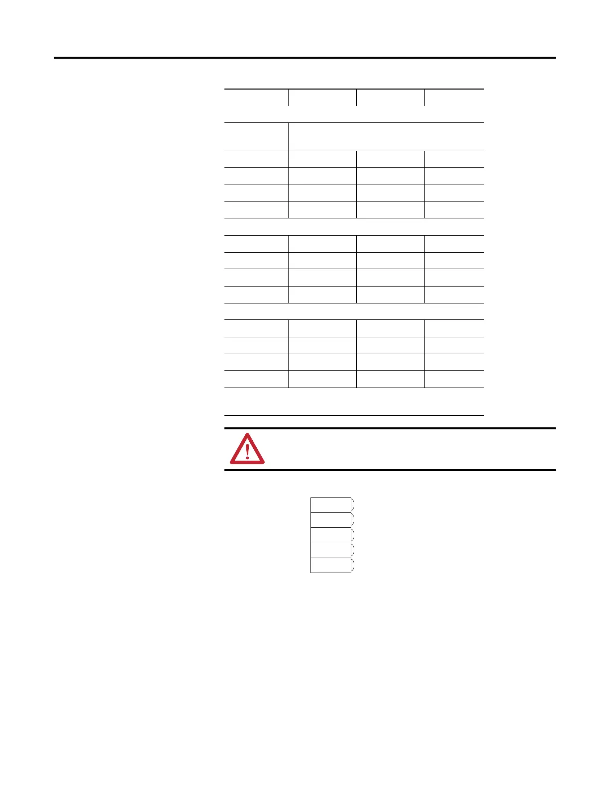
DeviceNet
Connection
Red
White
Bare
Blue
Black
-V
+V
CAN - High
Shield
CAN - Low

 Loading...


