EasyManua.ls Logo

Allen-Bradley 2080-IF4 User Manual

Allen-Bradley 2080-IF4
118 pages
To Next Page IconTo Next Page
To Previous Page IconTo Previous Page
Page #110 background imageLoading...
Page #110 background image
102 Rockwell Automation Publication 2080-UM004C-EN-E - March 2015
Appendix B Quickstart
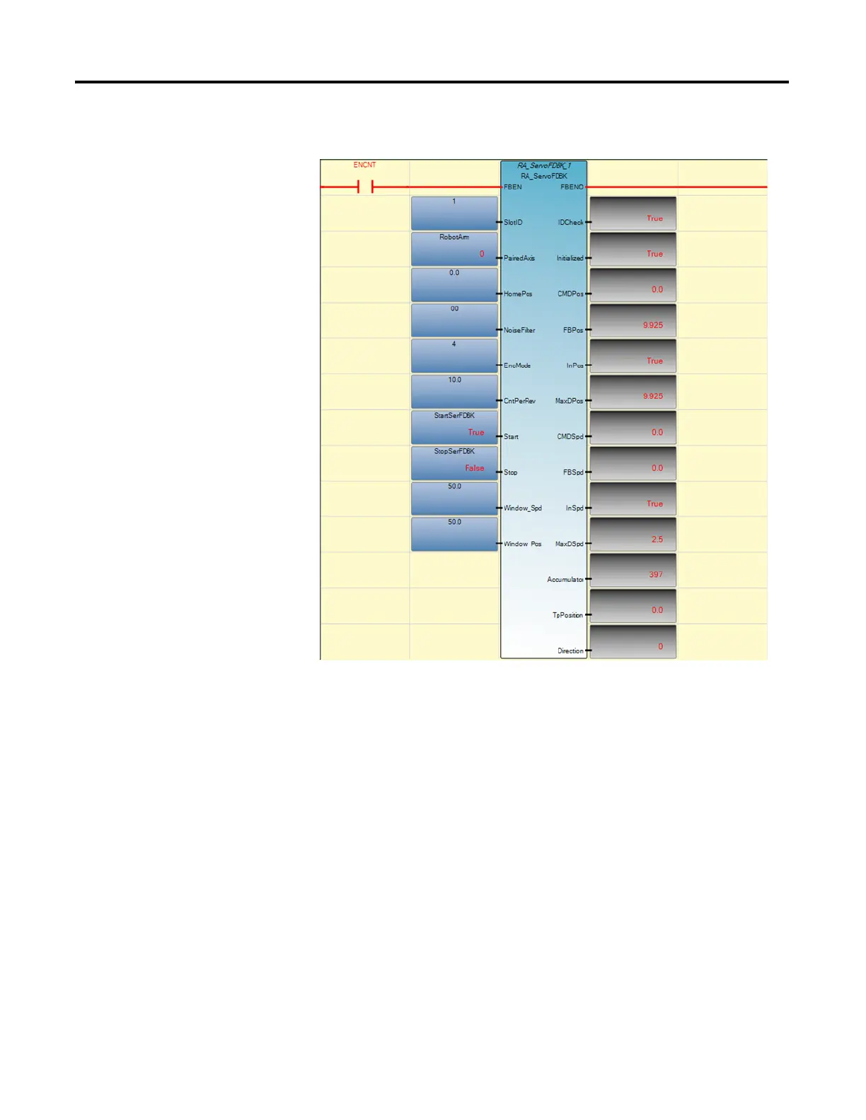
Execute the Function Block
Operation Sequence
A rising edge of FBEN causes the function block to start initializing steps.
When Initialized is done, Output Initialized changes to TRUE.
You can start the feedback process (Start counting) after Initialized is
TRUE. A rising edge of Start will trigger the feedback process.
Please note that if you want to get positioning information, you need to do
following steps to ensure that position information is in sync:
a. Initialize the RA_FDBKAxis function block.
b. Home the PTO axis to be monitored.
c. Once home is done, start the feedback process.
You can stop/pause the process and clear the MaxDPos and MaxDSpd by
giving a rising edge of Stop. If you want to disable the function block, you
need set it to Stop state first.
If FBEN is True and you start the feedback process from previous Stop
state, the function block will not be re-initialized. It will resume count
from previous accumulator value.

Table of Contents

Question and Answer IconNeed help?

Do you have a question about the Allen-Bradley 2080-IF4 and is the answer not in the manual?

Allen-Bradley 2080-IF4 Specifications

General IconGeneral
TypeAnalog Input Module
Analog Inputs4
Resolution16-bit
Input TypeVoltage/Current
Input Impedance Current250 Ω
Power Supply Voltage24 VDC
Current Input Range4 to 20 mA
Accuracy±0.1% of full scale
Operating Temperature-20 to 60 °C
Storage Temperature-40 to 85 °C
Relative Humidity5% to 95% (non-condensing)
Power Consumption1.5W
Voltage Input Range-10 to 10 V
Input Impedance Voltage1 MΩ

Summary

Important User Information

Safety Warnings and Symbols

Defines WARNING, ATTENTION, SHOCK HAZARD, BURN HAZARD, and IMPORTANT messages.

Chapter 1 Micro800 Plug-in Modules

Types of Micro800 Plug-in Modules

Categorizes plug-ins into Digital, Analog, Specialty, and Communication types.

Chapter 2 Install and Wire Your Module

Wiring Diagrams and Pin Designations

Provides pinout details for 12-pin and 8-pin terminal blocks and wiring considerations.

Chapter 4 High Speed Counter – 2080-MOT-HSC

User Defined Function Blocks (UDFBs)

Explains the purpose and parameters of UDFBs like RA_HSCPlugIn for HSC configuration.

Chapter 5 DeviceNet Plug-in – 2080-DNET20

Network Configuration and Wiring

Covers network setup, wiring requirements, and specifications for DeviceNet.

DeviceNet Function Blocks (UDFBs)

Introduces UDFBs for controlling DeviceNet scanners and nodes.

Appendix B Quickstart

Add and Configure Plug-ins in CCW

Guides users on configuring plug-ins using Connected Components Workbench.

Flash Upgrade Plug-in Firmware

Provides steps for updating the firmware of the 2080-DNET20 plug-in.

Appendix C Error Codes

Micro800 Plug-in Module Error Codes

Lists specific error codes for plug-in modules and recommended recovery actions.

Related product manuals