EasyManua.ls Logo

Allen-Bradley 2080-IF4 User Manual

Allen-Bradley 2080-IF4
118 pages
To Next Page IconTo Next Page
To Previous Page IconTo Previous Page
Page #54 background imageLoading...
Page #54 background image
46 Rockwell Automation Publication 2080-UM004C-EN-E - March 2015
Appendix 5 DeviceNet Plug-in – 2080-DNET20
Upon powerup, the scanner should be in IDLE Mode for the autoscan to start.
Wait until the autoscan process is complete before turning the scanner to RUN
Mode (that is, Run bit is TRUE).
Sample Code
RA_DNET_NODE_STATUS
This UDFB is used to read the node status of slave nodes in a DeviceNet network
where the 2080-DNET20 scanner is connected.
Error OUTPUT STRING Scanner error description.
ActiveNodes OUTPUT USINT Number of slave nodes in the network.
Scanlist0_62 OUTPUT LWORD Details on active node table, bit 0…62.
Bit 0: Represent Node 0.
Bit 62: Represent Node 62.
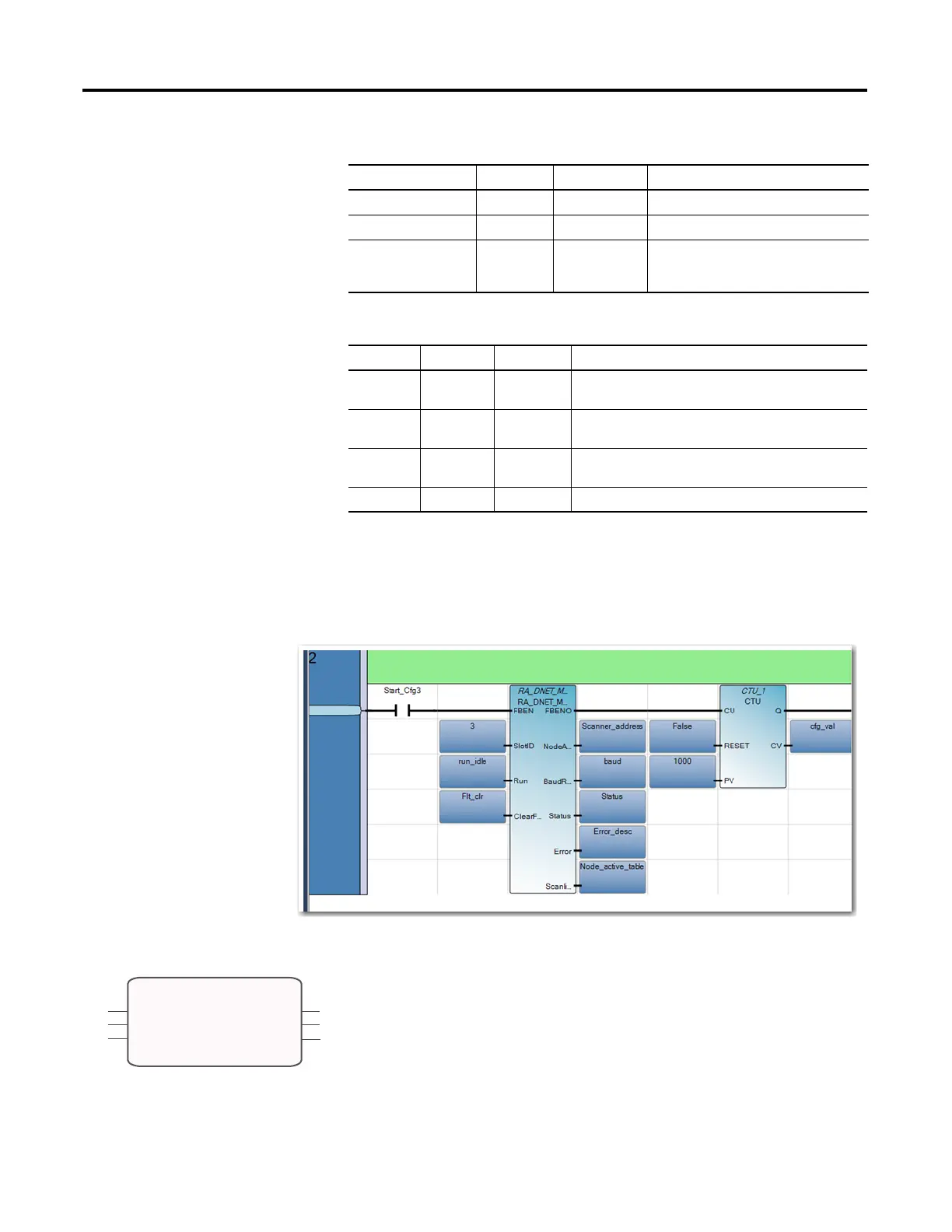
Sequence of Operation: RA_DNET_MASTER
Sequence Run Autoscan Description
1 False False Reinitializes scan list from the plug-in scanner if
FBEN = TRUE.
2 False True Triggers autoscan to scan the network after clearing
scan list.
3 False False Puts scanner to IDLE mode by disabling autoscan if
active node number = number of nodes in network.
4 True False Puts scanner to RUN mode.
RA_DNET_MASTER: Input and Output Parameters
Variable Name Type Data Type Description
FBEN
SlotID
NodeID
FBENO
RA_DNET_NODE_STATUS
Status
Error

Table of Contents

Question and Answer IconNeed help?

Do you have a question about the Allen-Bradley 2080-IF4 and is the answer not in the manual?

Allen-Bradley 2080-IF4 Specifications

General IconGeneral
TypeAnalog Input Module
Analog Inputs4
Resolution16-bit
Input TypeVoltage/Current
Input Impedance Current250 Ω
Power Supply Voltage24 VDC
Current Input Range4 to 20 mA
Accuracy±0.1% of full scale
Operating Temperature-20 to 60 °C
Storage Temperature-40 to 85 °C
Relative Humidity5% to 95% (non-condensing)
Power Consumption1.5W
Voltage Input Range-10 to 10 V
Input Impedance Voltage1 MΩ

Summary

Important User Information

Safety Warnings and Symbols

Defines WARNING, ATTENTION, SHOCK HAZARD, BURN HAZARD, and IMPORTANT messages.

Chapter 1 Micro800 Plug-in Modules

Types of Micro800 Plug-in Modules

Categorizes plug-ins into Digital, Analog, Specialty, and Communication types.

Chapter 2 Install and Wire Your Module

Wiring Diagrams and Pin Designations

Provides pinout details for 12-pin and 8-pin terminal blocks and wiring considerations.

Chapter 4 High Speed Counter – 2080-MOT-HSC

User Defined Function Blocks (UDFBs)

Explains the purpose and parameters of UDFBs like RA_HSCPlugIn for HSC configuration.

Chapter 5 DeviceNet Plug-in – 2080-DNET20

Network Configuration and Wiring

Covers network setup, wiring requirements, and specifications for DeviceNet.

DeviceNet Function Blocks (UDFBs)

Introduces UDFBs for controlling DeviceNet scanners and nodes.

Appendix B Quickstart

Add and Configure Plug-ins in CCW

Guides users on configuring plug-ins using Connected Components Workbench.

Flash Upgrade Plug-in Firmware

Provides steps for updating the firmware of the 2080-DNET20 plug-in.

Appendix C Error Codes

Micro800 Plug-in Module Error Codes

Lists specific error codes for plug-in modules and recommended recovery actions.

Related product manuals