Rockwell Automation Publication 2080-UM004C-EN-E - March 2015 27
High Speed Counter – 2080-MOT-HSC Appendix 4
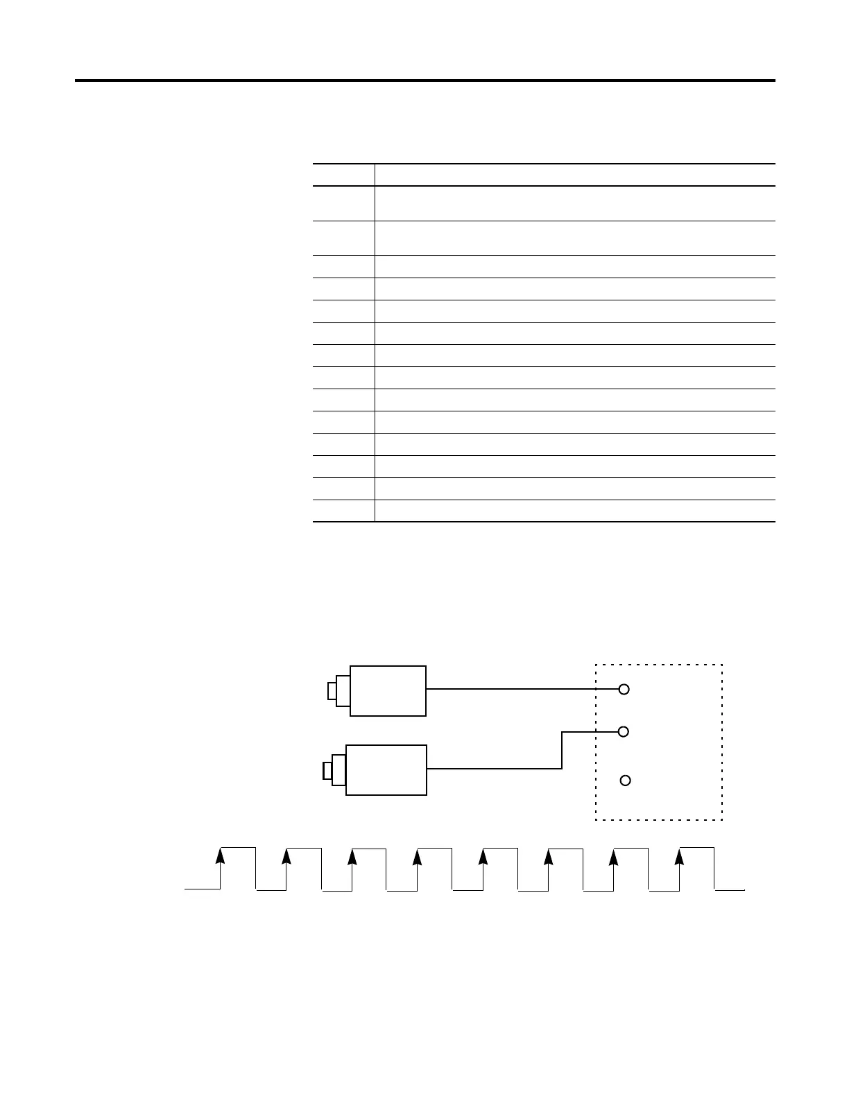
Up Counter
Pulses on A will cause the up counter (Counter 0). Also Pulses on B will cause the
up counter (Counter 1).
Input Operational Modes
Mode Description
0 Up Counter – The accumulator is immediately cleared (0) when it reaches the high
preset. A low preset cannot be defined in this mode.
1 Up Counter with external reset and hold – The accumulator is immediately cleared (0)
when it reaches the high preset. A low preset cannot be defined in this mode.
2 Counter with external direction.
3 Counter with external direction, reset, and hold.
4 Two input counter (up and down).
5 Two input counter (up and down) with external reset and hold.
6 Quadrature counter (phased inputs A and B).
7 Quadrature counter (phased inputs A and B) with external reset and hold.
8 Quadrature X4 counter (phased inputs A and B).
9 Quadrature X4 counter (phased inputs A and B) with external reset and hold.
10 Quadrature X2 counter (phased inputs A and B).
11 Quadrature X2 counter (phased inputs A and B) with external reset and hold.
12 Down Counter.
13 Down Counter with external reset and hold.
Input A
Input B
Input Z
Encoder or Sensor
Increment Pulse
(count up)
1
2
3
4
5
6
7
8
Counter 0
(Input A)
PresentCount 1
Encoder or Sensor
Increment Pulse
(count up)
 Loading...