204 Rockwell Automation Publication 520-UM001G-EN-E - September 2014
Appendix E Encoder/Pulse Train Usage and Position StepLogic Application
Wiring Notes
The encoder option card can supply 5V or 12V power (250 mA maximum) for
an encoder. Be sure the DIP switch is set properly for the encoder. In general, 12V
will provide higher noise immunity.
The encoder can handle 5V, 12V, or 24V inputs, but the pulse train can handle
only 24V inputs. The inputs will automatically adjust to the voltage applied and
no additional drive adjustment is necessary. If a single-channel input is used, it
must be wired between the A (signal) and A- (signal common) channels.
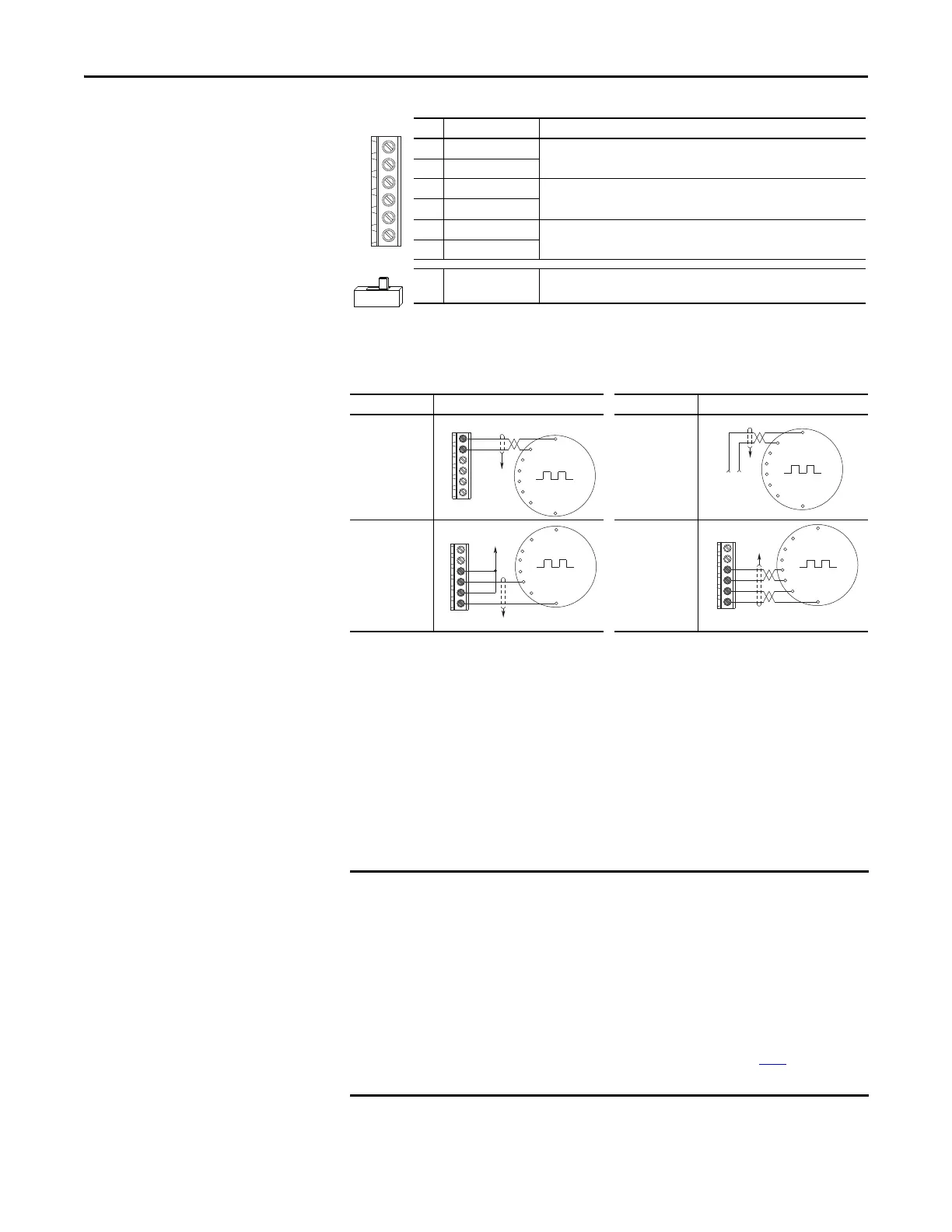
Encoder Wiring Examples
I/O Connection Example I/O Connection Example
Encoder Power
– Internal Drive
Power
Internal (drive)
12V DC, 250mA
Encoder Power
– External
Power Source
Encoder Signal
– Single-Ended,
Dual Channel
Encoder Signal
– Differential,
Dual Channel
+V
Cm
B-
B
A-
A
12V 5V
No. Signal Description
+V 5...12V Power
(1)(2)
(1) When using 12V Encoder power, 24V I/O power, maximum output current at I/O Terminal 11 is 50 mA.
(2) If Encoder requires 24V power, it must be supplied by an external power source.
Internal power source 250 mA (isolated).
Cm Power Return
B- Encoder B (NOT)
Quadrature B input.
B Encoder B
A- Encoder A (NOT)
Single channel, pulse train or quadrature A input.
A Encoder A
Output DIP switch selects 12 or 5 volt power supplied at terminals “+V” and “Cm”
for the encoder.
Common
+12V DC
(250 mA)
A
A-
B
B-
Cm
+V
to SHLD
+
Common
External
Power
Supply
to
SHLD
A NOT
A
B
B NOT
to SHLD
to Power Supply
Common
A
A-
B
B-
Cm
+V
to SHLD
A NOT
B
A
B NOT
A
A-
B
B-
Cm
+V
A quadrature encoder provides rotor speed and direction. Therefore, the
encoder must be wired such that the forward direction matches the motor
forward direction. If the drive is reading encoder speed but the position
regulator or other encoder function is not working properly, remove power to
the drive, then do one of the following:
• Swap the A and A (NOT) encoder channels.
• Swap the B and B (NOT) encoder channels.
• Swap any two motor leads.
Drives will fault when an encoder is incorrectly wired and A535
[Motor Fdbk
Type] is set to 5 “Quad Check”.

 Loading...


