34 Rockwell Automation Publication 520-UM001G-EN-E - September 2014
Chapter 1 Installation/Wiring
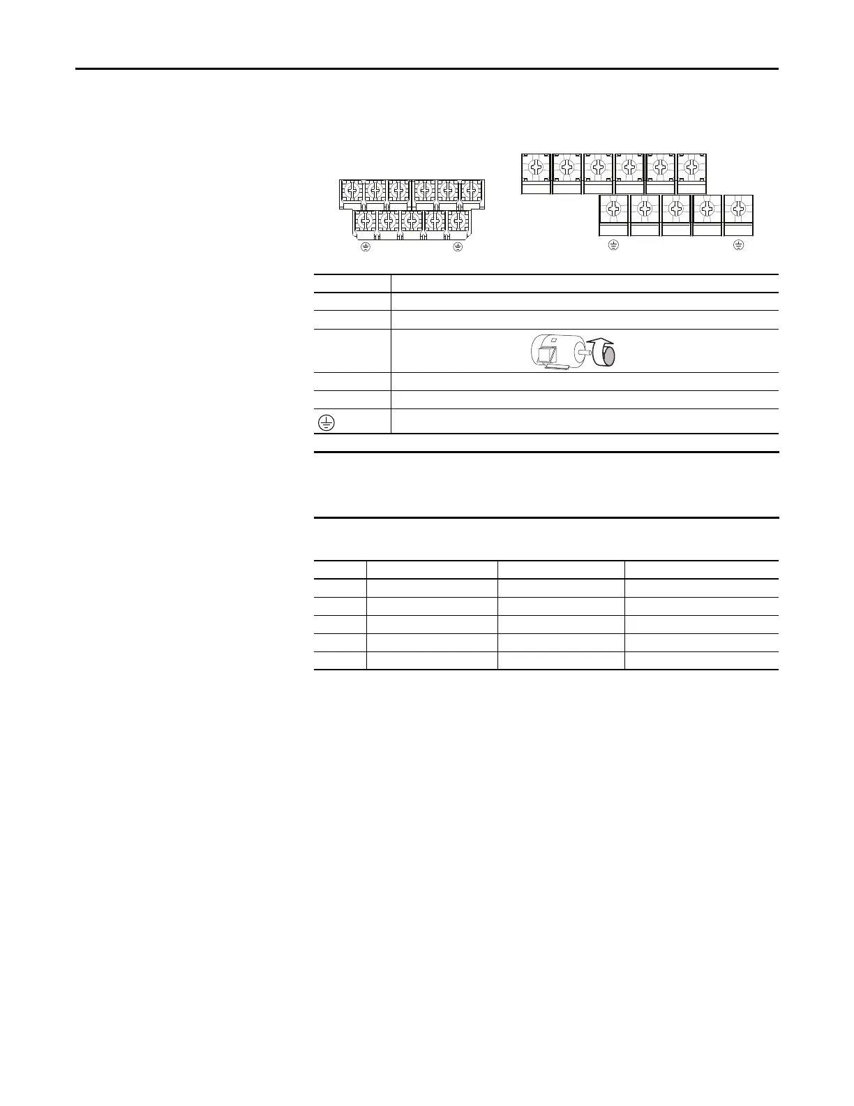
Power Terminal Block
Power Terminal Block
Terminal Description
R/L1, S/L2 1-Phase Input Line Voltage Connection
R/L1, S/L2, T/L3 3-Phase Input Line Voltage Connection
U/T1, V/T2, W/T3 Motor Phase Connection = Switch any two motor leads to change
forward direction.
DC+, DC- DC Bus Connection (except for 110V 1-Phase)
BR+, BR- Dynamic Brake Resistor Connection
Safety Ground - PE
Terminal screws may become loose during shipment. Ensure that all terminal
screws are tightened to the recommended torque before applying power to the
drive.
Power Terminal Block Wire Specifications
Frame Maximum Wire Size
(1)
(1) Maximum/minimum sizes that the terminal block will accept – these are not recommendations.
Minimum Wire Size
(1)
Torque
A5.3 mm
2
(10 AWG) 0.8 mm
2
(18 AWG) 1.76...2.16 Nm (15.6...19.1 lb-in.)
B8.4 mm
2
(8 AWG) 2.1 mm
2
(14 AWG) 1.76...2.16 Nm (15.6...19.1 lb-in.)
C8.4 mm
2
(8 AWG) 2.1 mm
2
(14 AWG) 1.76...2.16 Nm (15.6...19.1 lb-in.)
D13.3 mm
2
(6 AWG) 5.3 mm
2
(10 AWG) 1.76...2.16 Nm (15.6...19.1 lb-in.)
E26.7 mm
2
(3 AWG) 8.4 mm
2
(8 AWG) 3.09...3.77 Nm (27.3...33.4 lb-in.)
V/T2T/L3S/L2R/L1 U/T1 W/T3
V/T2T/L3S/L2R/L1 U/T1 W/T3
BR+
BR-
DC- DC+
BR+
BR-
DC-
DC+
Frame A, B, C & D Frame E

 Loading...


