40 Rockwell Automation Publication 520-UM001G-EN-E - September 2014
Chapter 1 Installation/Wiring
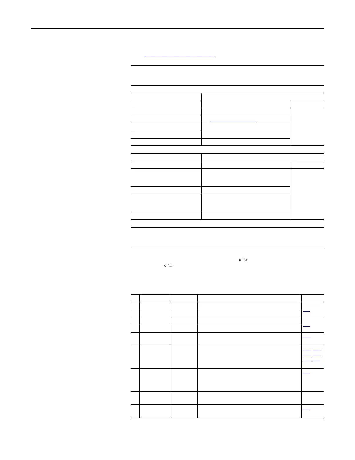
Control I/O Wiring Block Diagram Notes
(1) See Digital Input Selection for Start Source on page 47 for more information on configuring the digital inputs.
(2) Two wire control shown. For three wire control use a momentary input on I/O Terminal 02 to command a start. Use a
maintained input for I/O Terminal 03 to change direction.
(3) When using an opto output with an inductive load such as a relay, install a recovery diode parallel to the relay as shown, to prevent
damage to the output.
I/O Terminal 01 is always a stop input. The stopping mode is determined by the
drive setting. See the tables below for more information.
Start Method Stop Method
P046, P048, P050 [Start Source x] I/O Terminal 01 Stop Normal Stop
1 “Keypad” Coast Per P045
[Stop Mode]
2 “DigIn TrmBlk” See t062, t063 [DigIn TermBlk xx]
below
3 “Serial/DSI” Coast
4 “Network Opt” Coast
5 “EtherNet/IP” Coast
Start Method Stop Method
t062, t063 [DigIn TermBlk xx] I/O Terminal 01 Stop Normal Stop
48 “2-Wire FWD” t064 [2-Wire Mode] is set to:
• 0, 1, or 2 = Coast
• 3 = per P045 [Stop Mode]
Per P045
[Stop Mode]
49 “3-Wire Start” Per P045 [Stop Mode]
50 “2-Wire REV” t064 [2-Wire Mode] is set to:
• 0, 1, or 2 = Coast
• 3 = per P045 [Stop Mode]
51 “3-Wire Dir” Per P045 [Stop Mode]
The drive is shipped with a jumper installed between I/O Terminals 01 and 11.
Remove this jumper when using I/O Terminal 01 as a stop or enable input.
Control I/O Terminal Designations
No. Signal Default Description Parameter
R1 Relay 1 N.O. Fault Normally open contact for output relay.
t076
R2 Relay 1 Common Fault Common for output relay.
R5 Relay 2 Common Motor Running Common for output relay.
t081
R6 Relay 2 N.C. Motor Running Normally closed contact for output relay.
01 Stop Coast Three wire stop. However, it functions as a stop under all input
modes and cannot be disabled.
P045
(1)
02 DigIn TermBlk 02/
Start/Run FWD
Run FWD Used to initiate motion and also can be used as a programmable
digital input. It can be programmed with t062 [DigIn TermBlk
02] as three wire (Start/Dir with Stop) or two wire (Run FWD/
Run REV) control. Current consumption is 6 mA.
P045, P046,
P048, P050,
A544, t062
03 DigIn TermBlk 03/
Dir/Run REV
Run REV Used to initiate motion and also can be used as a programmable
digital input. It can be programmed with t063 [DigIn TermBlk
03] as three wire (Start/Dir with Stop) or two wire (Run FWD/
Run REV) control. Current consumption is 6 mA.
t063
04 Digital Common – Return for digital I/O. Electrically isolated (along with the digital
I/O) from the rest of the drive.
–
05 DigIn TermBlk 05 Preset Freq Program with t065 [DigIn TermBlk 05].
Current consumption is 6 mA.
t065

 Loading...


