18 Rockwell Automation Publication 6000-IN006F-EN-P - March 2018
Chapter 1 Drive Mechanical Installation
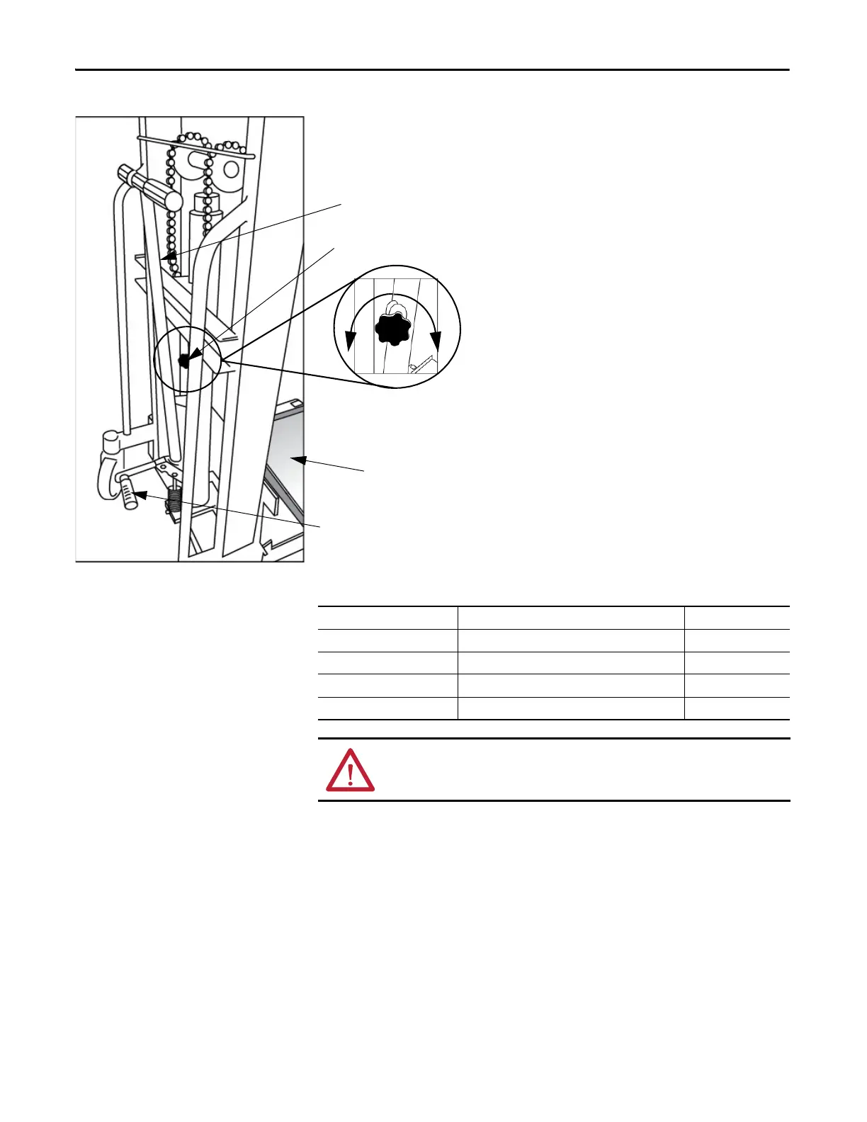
Figure 12 - Lift Cart Procedure
Table 4 - Power Module Specifications
Hand Crank
Foot Crank
Pressure Release Knob
1. Check the lift tray before use to ensure the tray
can be raised and lowered smoothly.
2. Rotate the Pressure Release Knob
counterclockwise to ensure that the tray is in
the lowest position.
3. Move the Power Module on the tray and lift
the module to the appropriate height using the
Foot Crank and complete the installation.
4. Rotate the Pressure Release Knob
counterclockwise to lower the tray to its
original position.
5. Repeat steps 1...4 to complete the installation
for all the Power Modules.
The Foot Crank raises the lift tray faster than
the Hand Crank. Use this to raise the Power
Module to just below the tray assembly in
the drive. Use the Hand Crank for final
precise positioning.
Lift tray
Release
pressure in
cylinder
Seal
pressure in
sylinder
Output Rating (Amps) Dimensions (HxWxD), approx. Weight, approx.
≤150 A 420 x 180 x 615 mm (16.5 x 7.1 x 24.2 in.) 20 kg (44.1 lb)
151...200 A 420 x 260 x 615 mm (16.5 x 10.2 x 24.2 in.) 25 kg (55.1 lb)
201...350 A 552.5 x 244.5 x 663 mm (21.8 x 9.6 x 26.1 in.) 70 kg (154 lb)
351...680 A 471 x 354 x 746 mm (18.5 x 13.9 x 29.4 in.) 95 kg (209 lb)
ATTENTION: Two people are required to handle the Power Modules.

 Loading...


