Rockwell Automation Publication 6000-IN006F-EN-P - March 2018 17
Drive Mechanical Installation Chapter 1
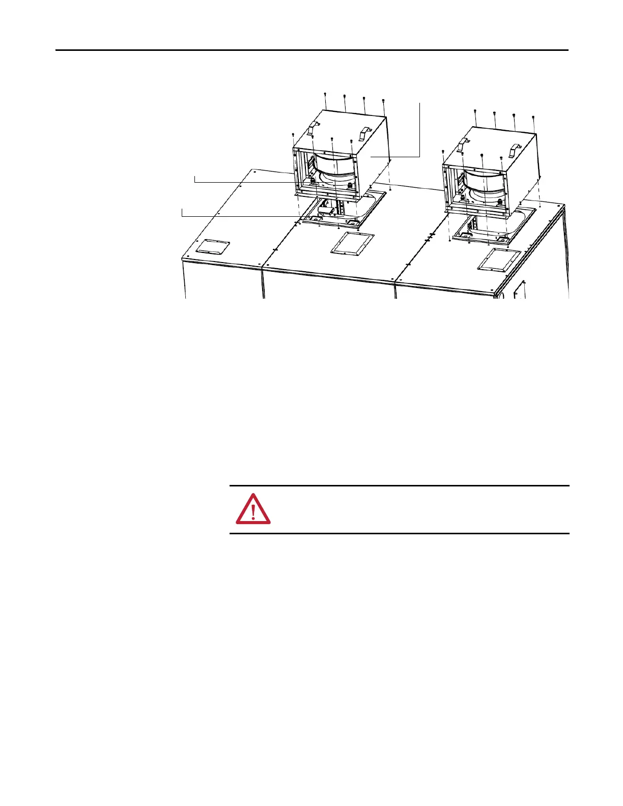
Figure 11 - Main Cooling Fan Housing, Type B
Install Power Modules (if
applicable)
Power Modules are available in a wide variety of amperage ratings relating to the
required motor current. Power Modules rated up to and including 350 A are
mounted in the drive and ship already installed.
Power Modules rated above 350 A are shipped separately, therefore site
installation and cable connection is needed. In this case, a lift cart is supplied and
shipped together with the other components.
Power Module Lift Cart
The lift cart’s hydraulic cylinder can be operated by either a hand or foot crank.
The lifting capacity is 400 kg (882 lb).
Main Cooling Fan housing
Aviation plug
Socket
Rear View
ATTENTION: Only authorized personnel should operate the lift cart. Keep hands
and feet away from the lifting mechanism. Do not stand under the lift tray
when in use. Store the lift cart with the tray fully lowered.

 Loading...


