38 Rockwell Automation Publication 6000-IN006F-EN-P - March 2018
Chapter 3 Drive Electrical Interconnection
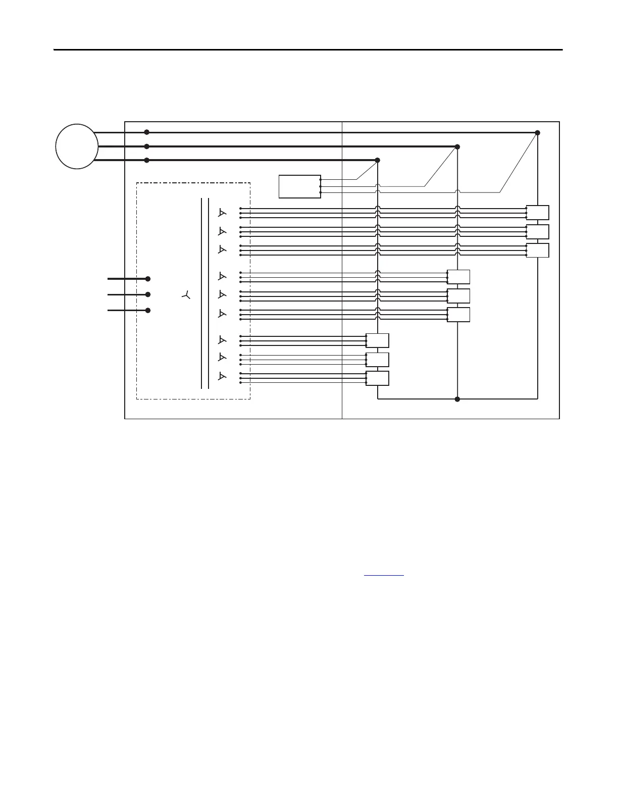
Refer to the Electrical Drawing for actual wire number designations.
Figure 25 - Power Cabling Overview (3.3 kV shown)
Connect Isolation
Transformer Secondary
Power Cables
Introduction
The isolation transformer’s three-phase primary coils are oriented A, B, and C
from left to right, as viewed from the front. The secondary windings are also
divided into three principal sections from top to bottom. The upper third are to
feed the power modules in the U output phase. The middle third are to feed the
power modules in the V output phase. The bottom third are to feed the power
modules in the W output phase (Figure 26
).
L1
L2
L3
1U
1V
1W
2U
2V
2W
3U
3V
3W
4U
4V
4W
5U
5V
5W
6U
6V
6W
7U
7V
7W
8U
8V
8W
9U
9V
9W
U
V
W
PC A1
PC A2
PC A3
PC B1
PC B2
PC B3
PC C1
PC C2
PC C3
U
V
W
Input power
3-phase AC
any voltage
Isolation Transformer
Motor
Voltage Sensing
Board
Isolation Transformer Cabinet Power Module/LV Control Cabinet

 Loading...


