32 Rockwell Automation Publication 6000-IN006F-EN-P - March 2018
Chapter 2 Drive Electrical Installation
Connect Control Power
Wiring
Introduction
Externally supplied control power is required to operate the drive. The standard
voltage supported is 220VAC/50 Hz. The other typical phase voltages of
230VAC, 110VAC, and 120VAC are also supported (50/60 Hz), but need to
be specified at the time of order. A minimum of 3 kVA is required to supply the
control circuit.
Wiring Routing and Connection
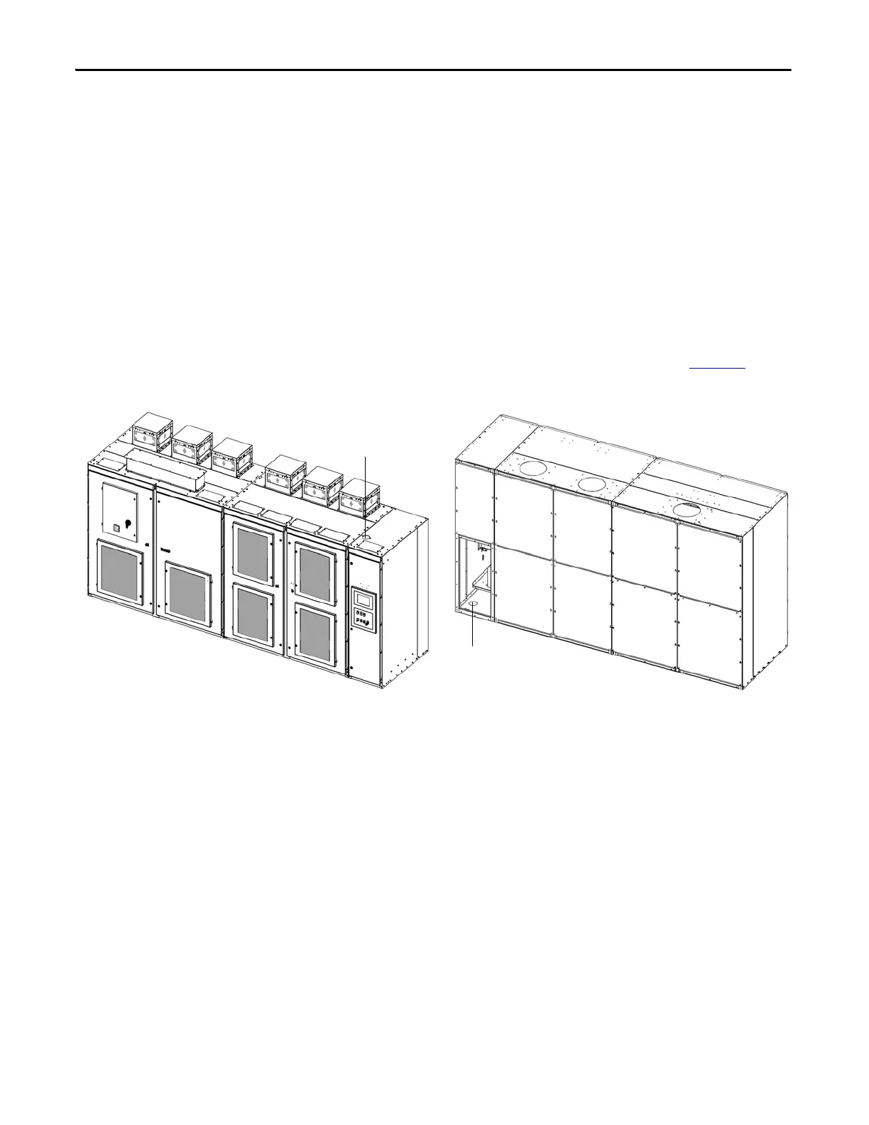
The opening for the control power wiring must be specified during the quotation
stage. Refer to the customer specific Dimension Drawing for the location of the
opening. The typical top/bottom entry design is shown below (Figure 21
).
Figure 21 - Control Power Wiring Opening, Type A
Cable entrance in bottom
rear of LV Control Cabinet
Bottom Entry Design
Cable entrance in top
of LV Control Cabinet
Top Entry Design

 Loading...


