Rockwell Automation Publication 6000-IN006F-EN-P - March 2018 47
Pre-Commissioning Appendix A
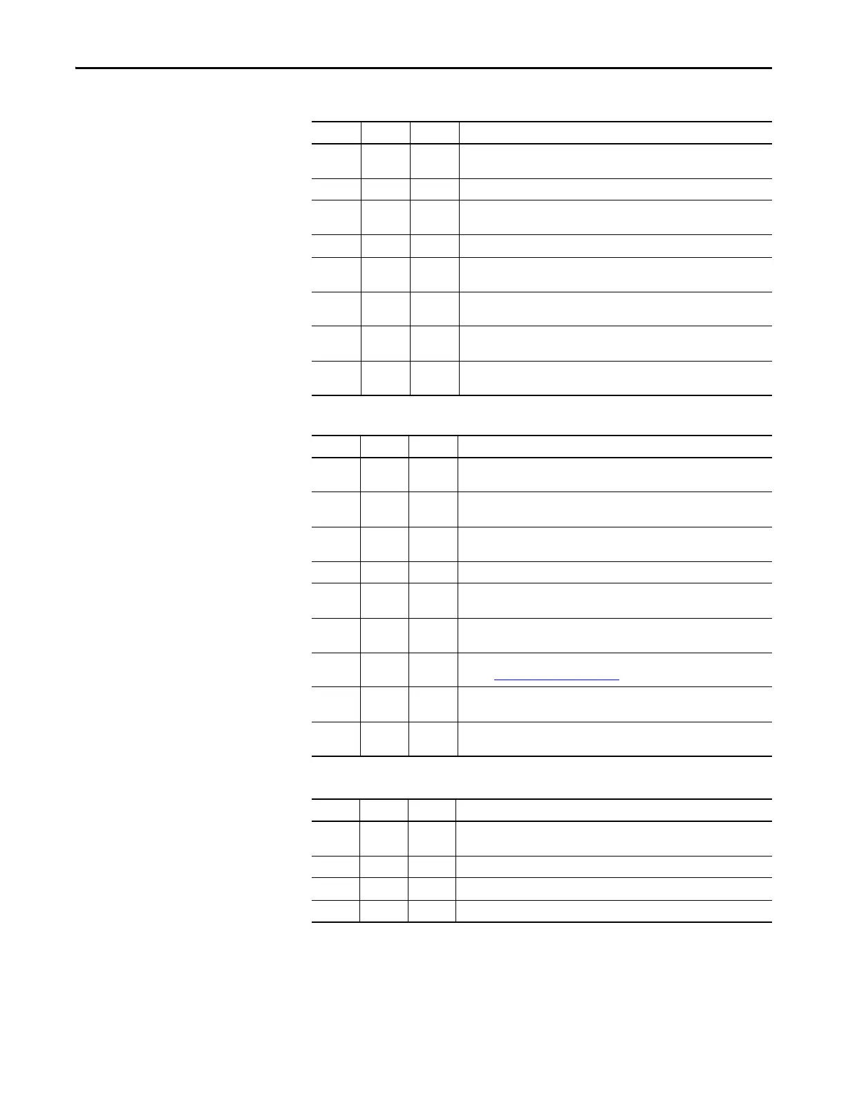
Table 10 - Control Wiring:
Table 11 - Power Wiring:
Table 12 - Interconnection Wiring
Initials Date Check
All low voltage wiring entering the drive is labeled, appropriate wiring diagrams
are available, and all customer interconnections are complete.
All AC and DC circuits are run in separate conduits.
All wire sizes used are selected by observing all applicable safety and national
and local electrical codes.
Remote I/O is correctly installed and configured (if applicable).
All 3-phase control wiring is within specified levels and has been verified for
proper rotation, UVW.
All single-phase control wiring is within specified levels and has grounded
neutrals.
Control lines must be shielded and grounded. Control and Power lines must run
in separate conduits.
The electrical safety interlock wiring to input circuit breaker is correctly
installed.
Initials Date Check
The power cable connections to the drive, motor and isolation transformer
adhere to national and local electrical codes.
The cable terminations, if stress cones are used, adhere to the appropriate
standards.
Appropriate cable insulation levels are adhered to, as per Rockwell Automation
specifications.
All shields for shielded cables must be grounded at the source end only.
If shielded cables are spliced, the shield must remain continuous and insulated
from ground.
All wire sizes used are selected by observing all applicable safety and national
and local electrical codes.
All power connections are torqued as per Rockwell Automation specifications.
Refer toTorque Requirements
on page 49.
All customer power cabling has been insulation resistance (IR) tested or hi-pot
tested before connecting to drive system.
Power wiring phase rotation has been verified per the specific electrical
diagrams supplied by Rockwell Automation.
Initials Date Check
The power cable connection between the Isolation Transformer and Power
Modules.
The motor cable connection to the three output buses.
The Voltage Sensing Board connections to the three output buses.
All low voltage connections to the Isolation Transformer Low Voltage panel.

 Loading...


