32 Rockwell Automation Publication 6000-TG100A-EN-P - September 2020
Chapter 3 Component Inspection and Test Procedures
2. Remove and retain the fourteen M6 x 16 hexagon combination screws
around the wire screen frame, and remove the frame.
3. Remove and retain the eight M4 x 12 hexagon combination screws, M4
nut washer, and lock washer that secure the L-shape fan housing bracket
and fan housing lid, and remove the bracket.
4. Remove and retain the eighteen M4 x 10 countersunk head screws that
secure the fan housing lid, and remove the lid.
5. Remove and retain the twelve M6 x 16 hexagon combination screws that
secure the horizontal louver, and remove the louver.
6. Disconnect the fan cables from the terminal block.
7. Turn the fan assembly housing upside down, and remove and retain the
eight M8 x 20 hexagon combination screws that secure the fan support
bracket, and remove the bracket.
8. Turn back the assembly, and remove and retain the six M10 x 25 and M6 x
16 hexagon combination screws that secure the fan, and remove the fan.
9. Install the fan in the reverse order of removal. Rotate the impeller by
hand to verify that there is no contact with the fan housing assembly.
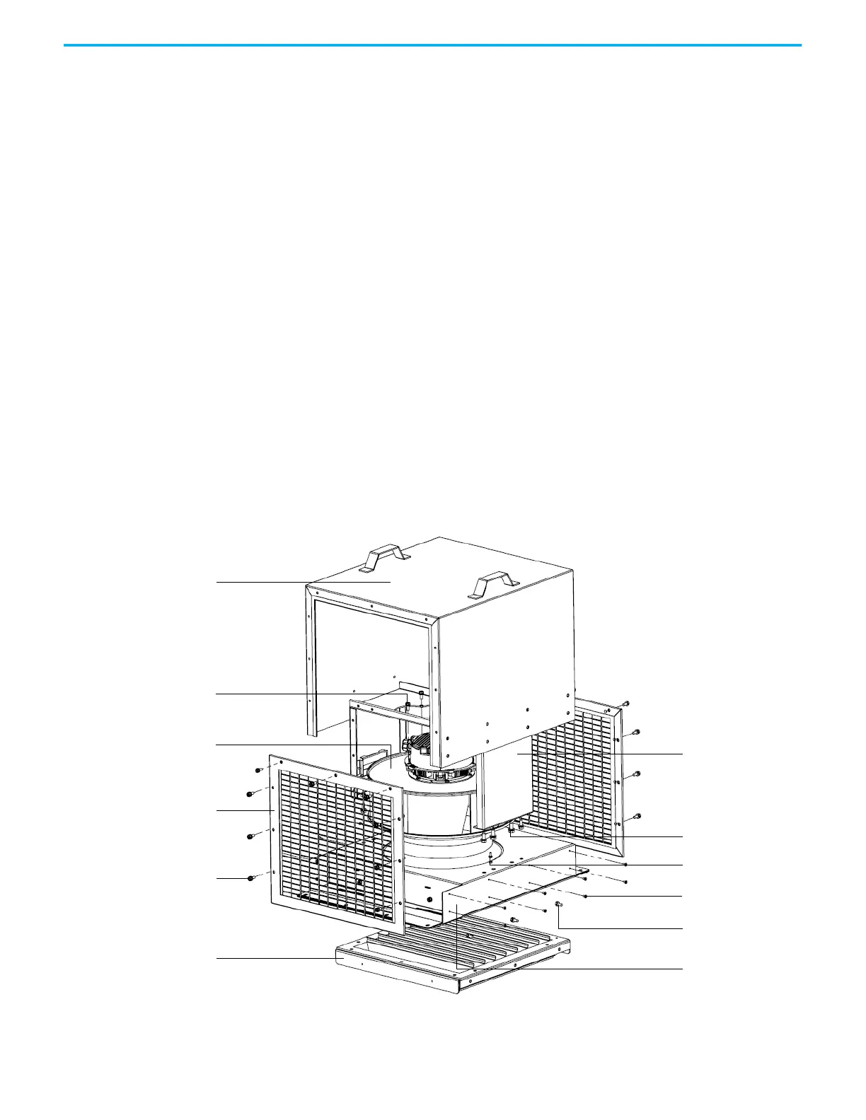
Replace Fan for B-Frame Fan Housing
1. Remove and retain 18 M6 x 16 hexagon socket screws around the wire
screen frame, and remove the frame.
2. Remove and retain 16 M4 x 8 countersunk head screws that secure the
fan housing lid, and remove the lid.
3. Remove and retain 10 M6 x 16 hexagon combination screws that secure
the horizontal louver, and remove the louver.
M6 x 16 hexagon combination
screw (5)
M6 x 16 hexagon socket
screw (18)
Fan housing lid
Fan support bracket
Wire screen frame
Horizontal louver
M8 x 20 hexagon
combination screw (8)
Terminal block
M4 x 12 hexagon
combination screw (4)
Fan housing assembly
M4 x 8 countersunk
head screw (16)
M6 x 16 hexagon
combination screw (10)
 Loading...


