62 Rockwell Automation Publication 6000-TG100A-EN-P - September 2020
Chapter 6 Power Cell Cabinet
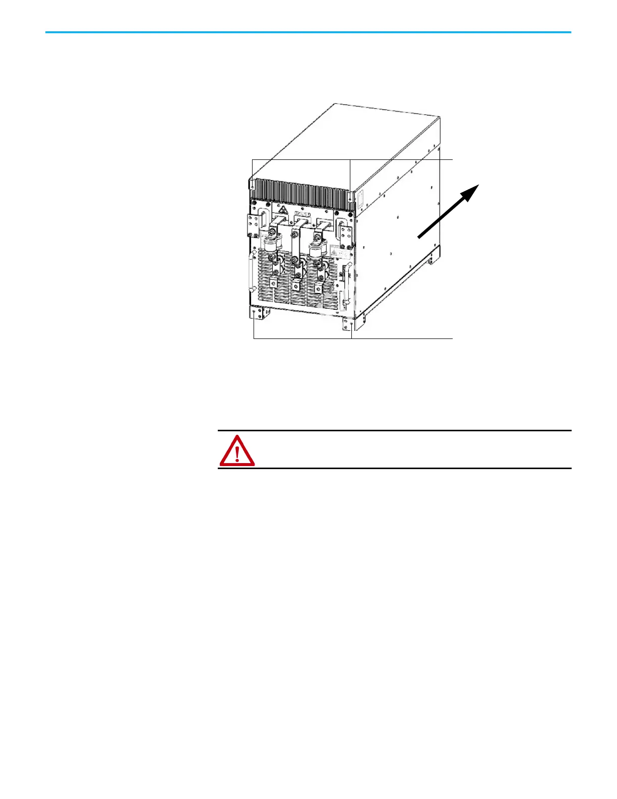
3. After installing the Power Cell in place, use the mounting brackets and
the M6 × 16 large flat pad galvanized nickel screws to fix the four corners,
as shown in the following illustration.
Using the Lift Cart Power Cells that are rated above 350 A are shipped separately, therefore site
installation and cable connection is needed. In this case, a lift cart is supplied
for power cell replacement.
The lift cart’s hydraulic cylinder can be operated by either a hand or foot crank.
The lifting capacity is 400 kg (882 lb).
Mounting points
438/560/680 A rating power
cell with two fuses shown
Mounting points
ATTENTION: Only authorized personnel should operate the lift cart. Keep
hands and feet away from the lifting mechanism. Do not stand under the lift
tray when in use. Store the lift cart with the tray fully lowered.
 Loading...


