Rockwell Automation Publication 6000-TG100A-EN-P - September 2020 47
Chapter 4 LV Control Cabinet
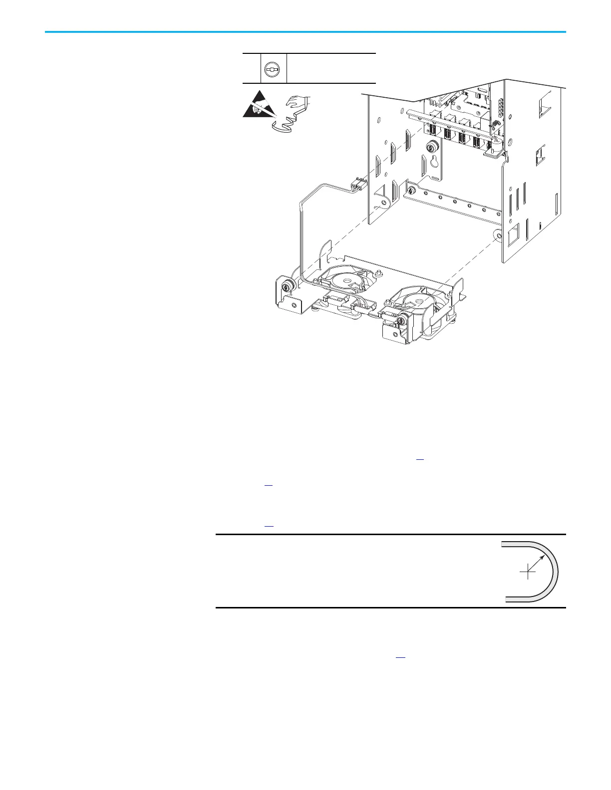
8. To install the control pod fan assembly, perform the operation in the
reverse order of removal.
Control Pod Replacement Replace the control pod assembly with kit part number PN-579789.
Follow these steps to replace the control pod.
1. Review the Product Advisories on page 11
.
2. Remove power from the system. See Remove Power from the System on
page 13
.
3. Open the control bay enclosure door.
4. Remove the control pod cover. See Control Pod Cover Removal on
page 35
.
5. Remove the fiber-optic cables from the cable management devices in the
control pod.
6. Remove the fiber transceiver circuit board. See Remove the Fiber
Transceiver Circuit Board on page 37
.
7. Unplug all cable harnesses to the main control board, control pod option
cards, power I/O board, and smart fiber interface board.
7
–
T20 or F - 6.4 mm (0.25 in.)
2.6 N•m (23 lb•in)
IMPORTANT
Minimum inside bend radius for fiber-optic cable is 50
mm (2 in.). Any bends with a shorter inside radius can
permanently damage the fiber-optic cable. Signal
attenuation increases as inside bend radius is
decreased.
 Loading...


