Rockwell Automation Publication 6000-TG100A-EN-P - September 2020 63
Chapter 6 Power Cell Cabinet
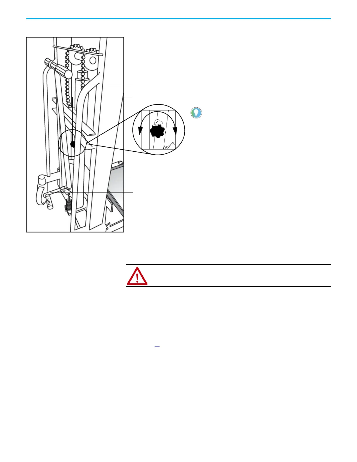
Figure 14 - Lift Cart Procedure
Replace Power Cell Fuses Follow these steps to replace the fuses on a power cell.
1. Remove the nut, lock washer, and washer from the top and bottom of the
fuse.
2. Remove the cables from the top and bottom of the fuse, and remove
another washer.
3. Install the new fuse, and replace cables and hardware in reverse order of
removal.
4. Torque all hardware to specifications. See Torque Requirements on
page 16
.
Hand Crank
Foot Crank
Pressure Release Knob
1. Check the lift tray before use to verify that
the tray can be raised and lowered
smoothly.
2. Rotate the Pressure Release Knob
counterclockwise to verify that the tray is
in the lowest position.
3. Move the Power Cell on the tray and lift the
module to the appropriate height using the
Foot Crank and complete the installation.
4. Rotate the Pressure Release Knob
counterclockwise to lower the tray to its
original position.
5. Repeat steps 1...4 to complete the
installation for all Power Cells.
The Foot Crank raises the lift tray
faster than the Hand Crank. Use this
to raise the Power Cell to just below
the tray assembly in the drive. Use
the Hand Crank for final precise
positioning.
Lift tray
Release
pressure in
cylinder
Seal
pressure in
cylinder
ATTENTION: Verify that the input circuit breaker feeding the drive is open.
Lockout and tagout the input circuit breaker before performing any work on
the drive or bypass units.
 Loading...


