EasyManuals Logo
Home>Allen-Bradley>DC Drives>PowerFlex 6000T

Allen-Bradley PowerFlex 6000T Hardware Service Manual

Allen-Bradley PowerFlex 6000T
70 pages
To Next Page IconTo Next Page
To Previous Page IconTo Previous Page
Page #54 background imageLoading...
Page #54 background image
54 Rockwell Automation Publication 6000-TG100A-EN-P - September 2020
Chapter 5 Isolation Transformer Cabinet
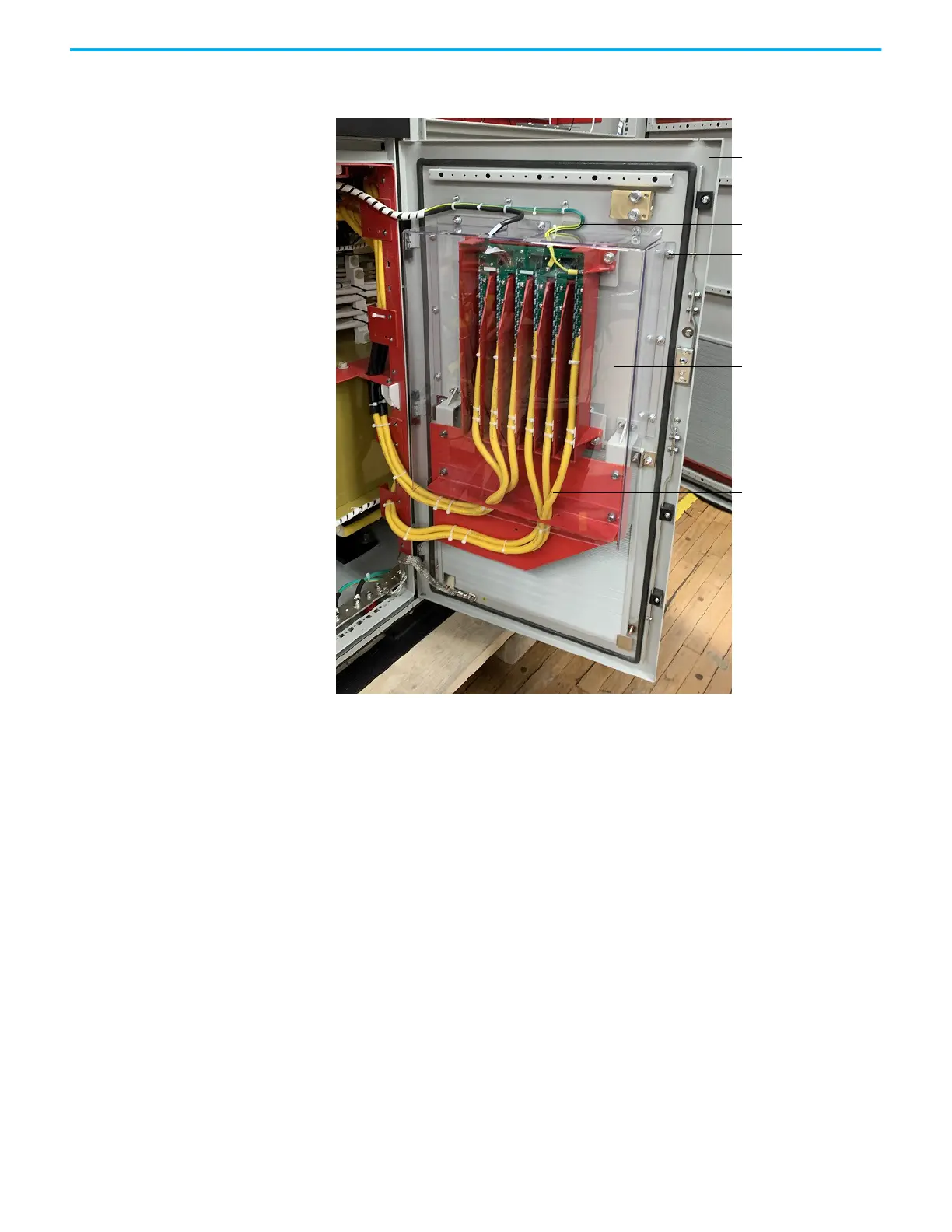
2. Remove and retain the nine M6 nuts, D6 washers, and D6 lock washers
that secure the VSB PC cover, and remove the cover.
3. Remove the six medium voltage cables, one ribbon cable, and two
grounds.
4. Remove and retain the four M8 x 30 bolts and washers that secure the
VSB, and remove the VSB.
Junction cabinet front door
VSB signal wires
M6 nuts, washers, and
lock washers (9)
VSB PC cover
VSB cables

Table of Contents

Other manuals for Allen-Bradley PowerFlex 6000T

Questions and Answers:

Question and Answer IconNeed help?

Do you have a question about the Allen-Bradley PowerFlex 6000T and is the answer not in the manual?

Allen-Bradley PowerFlex 6000T Specifications

General IconGeneral
BrandAllen-Bradley
ModelPowerFlex 6000T
CategoryDC Drives
LanguageEnglish

Related product manuals