2-82 Direction Control
PowerFlex 700 Firmware 3.001 (& later) Enhancements
Certain digital output enhancements have been included in firmware version
3.001 (and later) for the PowerFlex 700 Vector Control drive. These
include:
• Digital output control via Datalink
Parameter Controlled Digital Outputs
Enables control of the digital outputs through the Data In parameters.
Example
Digital Output 2 controlled by Data In B1
Setup
• [Data In B1], parameter 302 = 379 ([Dig Out Setpt] as the Data In target)
• [Digital Out2 Sel], parameter 384 = 30 "Param Cntl"
When Bit 1 of Data In B1 =1 Digital Out 2 will be energized.
Direction Control Direction control of the drive is an exclusive ownership function. Thus only
one device can be commanding/controlling direction at a time and that
device can only command one direction or the other, not both. Direction is
defined as the forward (+) or reverse (–) control of the drive output
frequency, not motor rotation
. Motor wiring and phasing determines its CW
or CCW rotation. Direction of the drive is controlled in one of four ways:
1. 2-Wire digital input selection such as Run Forward or Run Reverse
(Figure 2.17 on page 2-77
).
2. 3-Wire digital input selection such as Forward/Reverse, Forward or
Reverse (Figure 2.16 on page 2-77
).
3. Control Word bit manipulation from a DPI device such as a
communications interface. Bits 4 & 5 control direction. Refer to the
Logic Command Word information in Appendix A of the PowerFlex 70
or 700 User Manual.
4. The sign (+/-) of a bipolar analog input.
Direction commands by various devices can be controlled using the
[Direction Mask]. See page 2-114
for details on masks.
Refer to Digital Inputs
on page 2-61 and Analog Inputs on page 2-9 for
more detail on the configuration and operating rules for direction control.
INPUTS & OUTPUTS
Digital Outputs
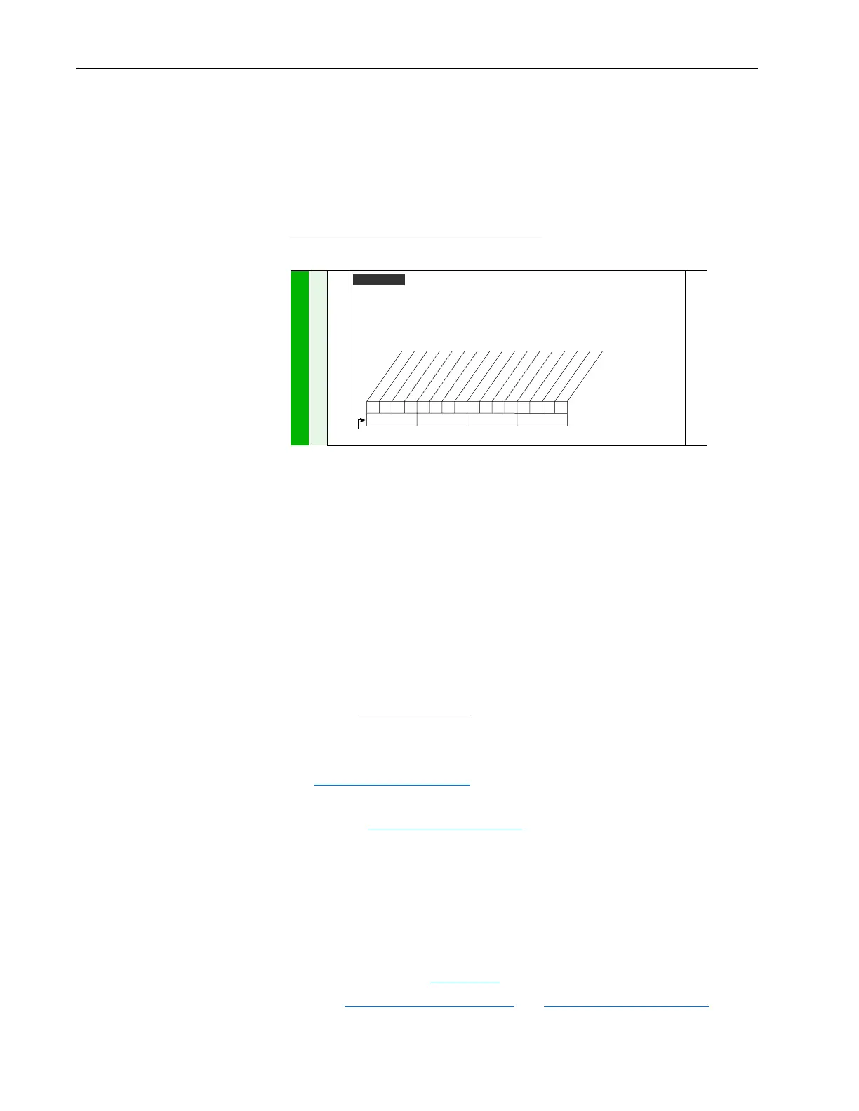
379 [Dig Out Setpt]
Sets the digital output value from a communication device.
Example
Set [Data In B1] to “379.” The first three bits of this value will determine the setting
of [Digital Outx Sel] which should be set to “24, Param Cntl.”
380
Vector v3
00x 0xxxxxxxxxxxx
10 01234567891112131415
1 = Output Energized
0 = Output De-energized
x = Reserved
Bit #
Net DigOut1
Net DigOut2
Net DigOut3

 Loading...


