2-52 Carrier (PWM) Frequency
Carrier (PWM)
Frequency
See page 1-3 for derating guidelines as they relate to carrier frequency.
In general, the lowest possible switching frequency that is acceptable for
any particular application is the one that should be used. There are several
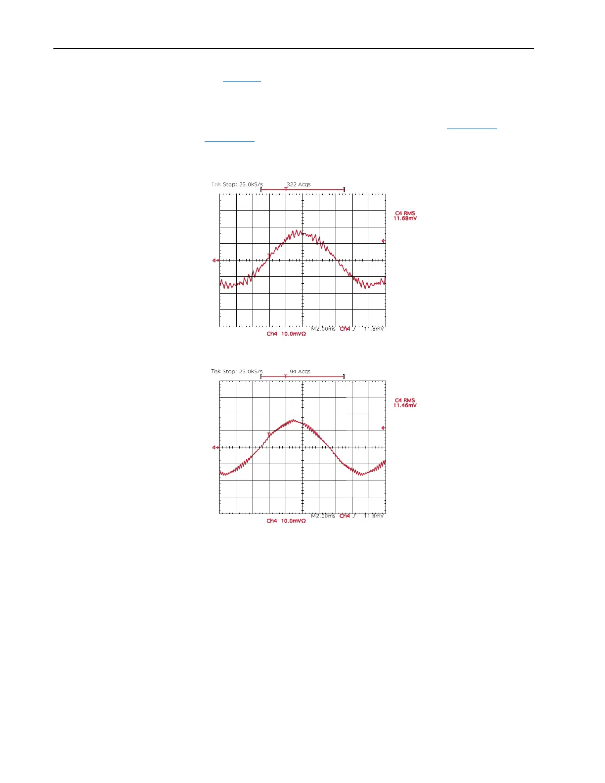
benefits to increasing the switching frequency. Refer to Figure 2.14
and
Figure 2.15
. Note the output current at 2 kHz and 4 kHz. The “smoothing”
of the current waveform continues all the way to 10 kHz.
Figure 2.14 Current at 2 kHz PWM Frequency
Figure 2.15 Current at 4 kHz PWM Frequency
The benefits of increased carrier frequency include less motor heating and
lower audible noise. An increase in motor heating is considered negligible
and motor failure at lower switching frequencies is very remote. The higher
switching frequency creates less vibration in the motor windings and
laminations thus, lower audible noise. This may be desirable in some
applications.
Some undesirable effects of higher switching frequencies include derating
ambient temperature vs. load characteristics of the drive, higher cable
charging currents and higher potential for common mode noise.
A very large majority of all drive applications will perform adequately at
2-4 kHz.

 Loading...


