Cable, Control 2-51
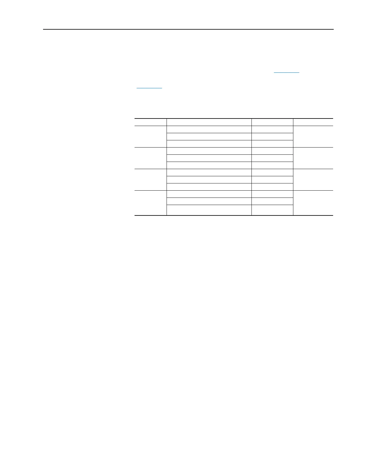
If [Bus Reg Mode A], parameter 161 is set to “Both-DB 1st”
Both regulators are enabled, and the operating point of the Dynamic Brake
Regulator is lower than that of the Bus Voltage Regulator. The Bus Voltage
Regulator setpoint follows the “DB Turn On” curve (Table 2.C
). The
Dynamic Brake Regulator follows the “DB Turn On” and turn off curves
(Table 2.C
). For example, with a DC Bus Memory at 684V DC, the Bus
Voltage Regulator setpoint is 750V DC and the Dynamic Brake Regulator
will turn on at 750V DC and back off at 742V DC.
Table 2.D
Cable, Control Refer to “Wiring and Grounding Guidelines for Pulse Width Modulated
(PWM) AC Drives,” publication DRIVES-IN001 for detailed information
on Cable, Control.
Cable, Motor Lengths Refer to “Wiring and Grounding Guidelines for Pulse Width Modulated
(PWM) AC Drives,” publication DRIVES-IN001 for detailed information
on Cable, Motor Lengths.
Cable, Power Refer to “Wiring and Grounding Guidelines for Pulse Width Modulated
(PWM) AC Drives,” publication DRIVES-IN001 for detailed information
on Cable, Power.
CabIe Trays and
Conduit
Refer to “Wiring and Grounding Guidelines for Pulse Width Modulated
(PWM) AC Drives,” publication DRIVES-IN001 for detailed information
on Cable Trays and Conduit.
Voltage Class DC Bus Memory Bus Reg Curve #1 Bus Reg Curve #2
240 < 325V DC Memory + 50V DC Curve 1 – 4V DC
325V DC ≤ DC Bus Memory ≤ 342V DC 375V DC
> 342V DC Memory + 33V DC
480 < 650V DC Memory + 100V DC Curve 1 – 8V DC
650V DC ≤ DC Bus Memory ≤ 685V DC 750V DC
> 685V DC Memory + 65V DC
600 < 813V DC Memory + 125V DC Curve 1 – 10V DC
813V DC ≤ DC Bus Memory ≤ 856V DC 937V DC
> 856V DC Memory + 81V DC
600/690V
PowerFlex 700
Frames 5 & 6
Only
< 933V DC Memory + 143V DC Curve 1 – 11V DC
933V DC ≤ DC Bus Memory ≤ 983V DC 1076V DC
> 983V DC Memory + 93V DC

 Loading...


