18 Rockwell Automation Publication 750-QS001A-EN-P - March 2015
Step 5: Special Considerations
Step 5: Special Considerations
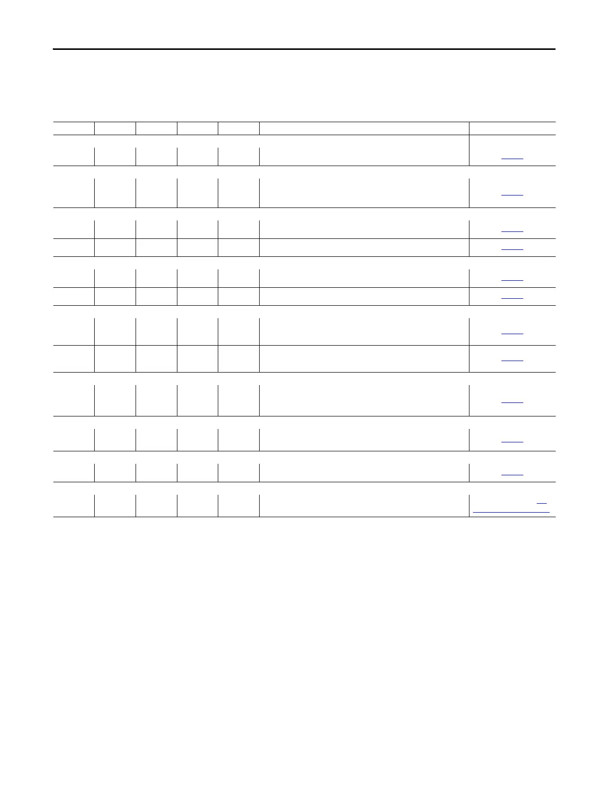
Drive 1 Drive 2 Drive 3 Drive 4 Drive 5 Description Details
Dynamic Brake
❑ ❑ ❑ ❑ ❑ Dynamic brake resistor connected to BR1 and BR2.
page
66
Accel and Decel Rates
❑ ❑ ❑ ❑ ❑ Accel and decel rates are set according to load inertia.
Decel rate can affect the need for dynamic braking.
page
68
Analog Output
❑ ❑ ❑ ❑ ❑ PowerFlex 753 connected to TB1 terminals Ao0±.
page 74
❑ ❑ ❑ ❑ ❑ Expansion I/O module connected to Ao0±.
page 74
Digital Output
❑ ❑ ❑ ❑ ❑ PowerFlex 753 main control board connects to TD1 (TO0) as appropriate.
page 75
❑ ❑ ❑ ❑ ❑ Expansion I/O module connected to TB1 (TO and TC or T1) as appropriate.
page 75
Relay Output
❑ ❑ ❑ ❑ ❑ PowerFlex 753 main control board connected to TB2 (R0C and R0NO or
R0NC) as appropriate.
page
76
❑ ❑ ❑ ❑ ❑ Expansion I/O module connected to TB2 (R0C and R0NO or R0NC) as
appropriate.
page
76
Disable HIM Function
❑ ❑ ❑ ❑ ❑
Option to restrict logic control (start, jog, direction) via the HIM, if the user
requires to only use other discrete input or communications controlled
start/run, jog, and direction commands.
page 77
HIM CopyCat Function
❑ ❑ ❑ ❑ ❑
Option to upload individual parameter sets for the host drive or any of its
connected peripherals into the HIM.
page 78
Motor Overload
❑ ❑ ❑ ❑ ❑
Adjust motor overload protection as appropriate.
page 82
Type of Communications Other than EtherNet/IP
❑ ❑ ❑ ❑ ❑ Communication options other than EtherNet/IP.
See the publications in
For
More Information on page 6.

 Loading...


