Rockwell Automation Publication 750-QS001A-EN-P - March 2015 75
Reference Section
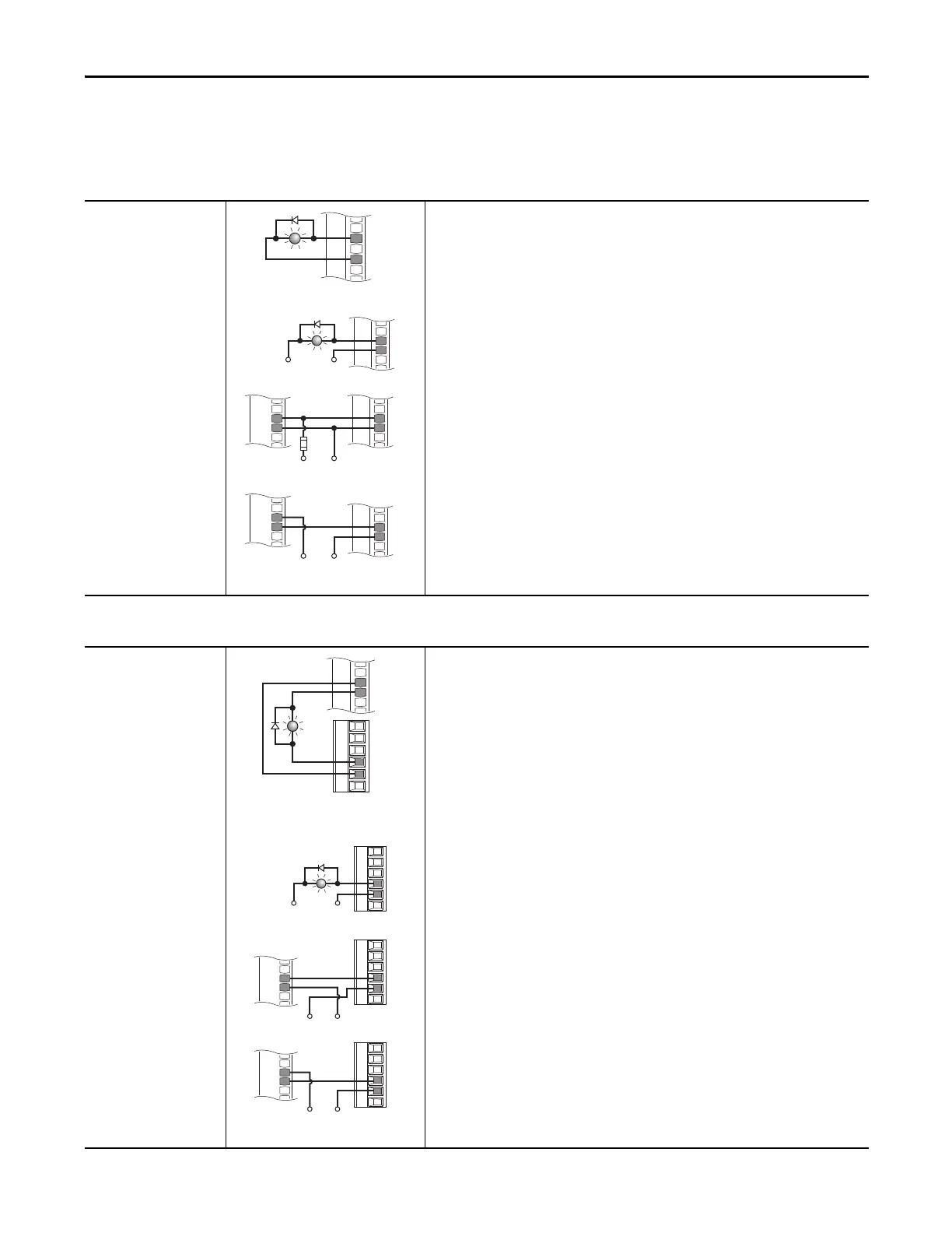
Digital Output Wiring
Table 52 - 753 Main Control Board Digital Output Wiring
Digital Output
Internal Supply
753 Main Control Board TB1
Set Selection
Port 0: P240 [TO0 Sel] = Port 0: P935 [Drive Status 1], bit 7= Faulted
View Results
Port 0: P225 [Dig Out Sts]
When TO is On, IN-O is Off.
Digital Output
External Supply
753 Main Control Board TB1
Table 53 - 750-Series I/O Module TB1 Digital Output Wiring
Digital Output
Internal Supply
20-750-2263C-1R2T
750-Series I/O Module TB1
750-Series I/O Module TB2
Set Selection
Port 4 (or port where your I/O module is installed): P20 [TO0 Sel] = Port 0: P935 [Drive Status 1],
bit 7= Faulted
View Results
Port 4 (or port where your I/O module is installed): P5 [Dig Out Sts]
Digital Output
External Supply
20-750-2263C-1R2T
750-Series I/O Module TB2
T0
24VC
+24V
5 kΩ
2 W
T0
24VC
+24VDC
PLC
1756-1B16
IN-0
GND-0
T0
24VC
+24VDC
PLC
1756-1V16
DC-0+
IN-0
24VC
+24V
T0
TC
T1
T0
TC
T1
+24V
T0
TC
T1
T0
TC
T1
+24VDC
PLC
1756-1B16
IN-0
GND-0
+24VDC
PLC
1756-1V16
DC-0+
IN-0

 Loading...


