10 Rockwell Automation Publication 750-QS001A-EN-P - March 2015
Step 2: Validate the Drive Installation
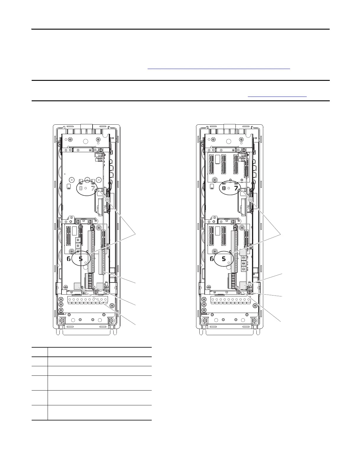
Where are Signal Sources Connected?
Use this diagram to help determine where signal sources are connected in each of your drives.
You will need this information when you get to
Step 4: Set Up Speed Reference and Start/Stop on page 17.
The 750-Series drive uses the term ‘Port’ to designate (in software) the physical location where hardware is located for ease of
selecting hardware or functions to program. For more information on port locations, see
Drive Device Ports on page 33.
Item Description
(1) Terminal block TB1, PowerFlex 753 drives.
(2) Embedded EtherNet/IP, PowerFlex 755 drives.
(3) Expansion I/O module, PowerFlex 753 and 755 drives.
(Port 4 installation shown.)
(4) Communication network module, P
owerFlex 753 drives.
(Port 6 installation shown.)
(5) Terminal block TB1 on PowerFlex 755 drive is located behind
the Ethernet
port.
Ao0-
Ao0+
10VC
+10V
Ai0-
Ai0+
Ptc-
Ptc+
To0
24VC
+24V
Di C
Di 1
Di 2
Sh
Sh
PTC–
PTC+
Ao0–
Ao0+
Ao1–
Ao1+
–10V
10VC
+10V
Ai0–
Ai0+
Ai1–
Ai1+
24VC
+24V
DiC
Di0
Di1
Di2
Di3
Di4
Di5
Sh
Sh
PTC–
PTC+
Ao0–
Ao0+
Ao1–
Ao1+
–10V
10VC
+10V
Ai0–
Ai0+
Ai1–
Ai1+
24VC
+24V
DiC
Di0
Di1
Di2
Di3
Di4
Di5
PowerFlex 753
PowerFlex 755
(1)
(3)
(4)
(2)
(3)
Port Location
Examples
Port Location
Examples
(5)

 Loading...


