Rockwell Automation Publication 750-QS001A-EN-P - March 2015 63
Reference Section
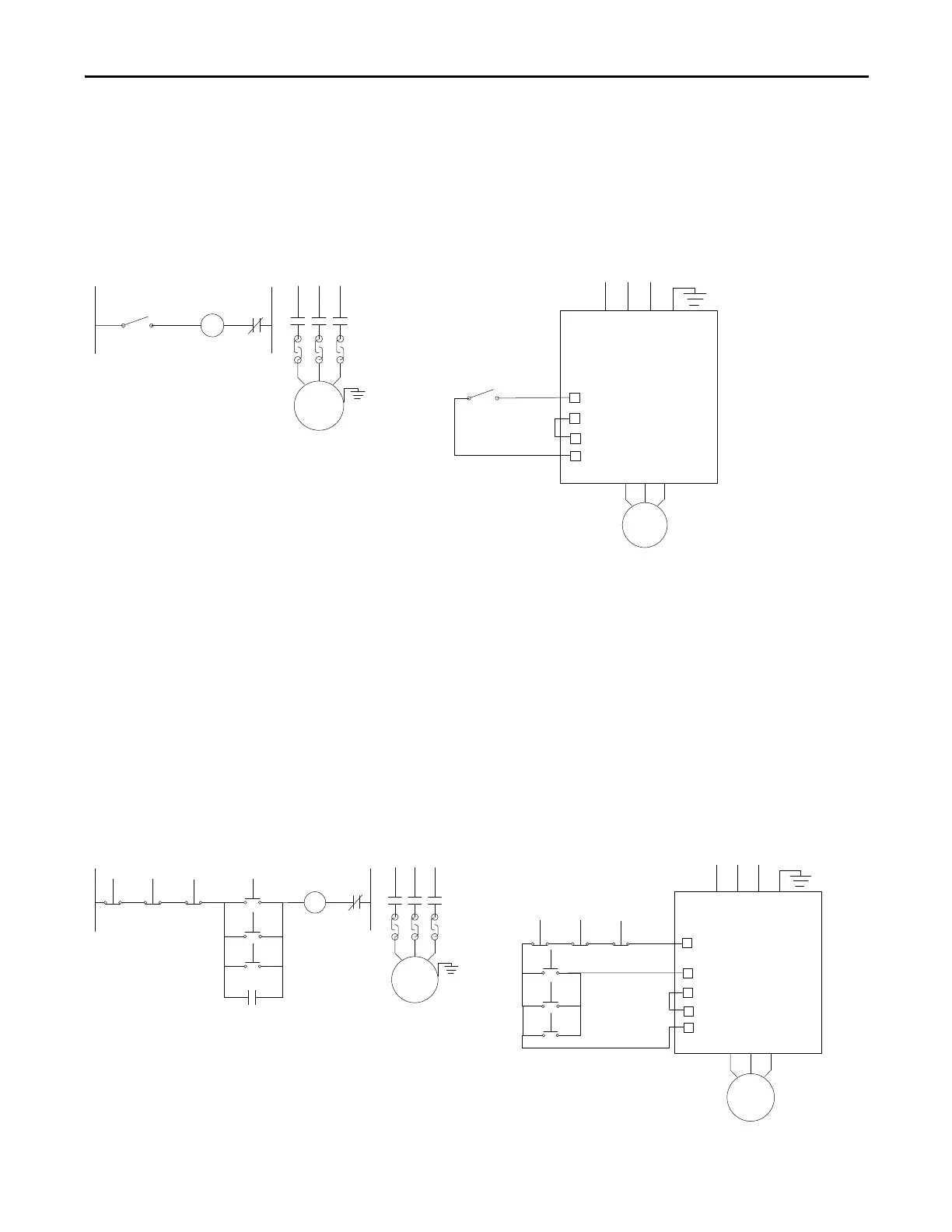
2-Wire and 3-Wire Control
The two types of ladder control circuits commonly used are the 2-wire control circuit and the 3-wire control circuit.
The 2-wire control circuit uses “maintained” contact devices to control the drive/motor. A typical 2-wire control circuit is
show
n in the following figure.
A 2-wire control circuit consists of a normally open “maintained” contact device that, when closed, energizes the coil of a
ma
gnetic motor starter. This in turn energizes the connected motor load, or in the case of VFD, initiates a Run command
to energize the motor load. The 2-wire control circuit provides what is known as “low-voltage release.” In the event of a
power failure, the magnetic motor starter or VFD shuts down. When power is restored, the magnetic motor starter or VFD
automatically reenergizes, provided that none of the maintained contact devices have changed state.
This can be quite advantageous in applications such as refrigeration, air conditioning, or remote pump stations where you
do not nee
d someone to restart the equipment after a power failure. It can, however, be extremely dangerous in applications
where equipment automatically starts, placing the operator in danger.
The 3-wire control circuit uses “momentary” contact devices to control the driver/motor starter. A typical 3-wire control
cir
cuit is shown in the following figure.
2-Wire Control on a Motor Starter
2-Wire Control on a Drive
Stop/Start or Run
Motor
Motor
VFD
DI0 Run
24V Common
Dig In Common
+24V DC
Stop/Start
3-Wire Control on a Motor Starter
3-Wire Control on a Drive
Motor
Motor
VFD
DI1 Run
24V Common
Dig In Common
+24V DC
DI0 Run
Stop Stop Stop
Stop Stop Stop
Start
Start
Start
Start
Start
Start

 Loading...


