Rockwell Automation Publication 750-QS001A-EN-P - March 2015 9
Step 2: Validate the Drive Installation
Verify Power Jumper Configuration
PowerFlex 750-Series drives contain protective MOVs and common mode capacitors that are referenced to ground. To
guard against drive damage and/or operation problems, these devices must be properly configured.
Record that the power jumper configuration for each drive is correct.
Verify I/O Wiring
To properly configure a drive, you need to know the source of the speed reference and the start/stop commands. There are
three places where signal sources (such as push buttons and potentiometers) are connected to the drive.
1. The drive’s main control board.
• Terminal block TB1 on a PowerFlex 753
• Embedded EtherNet/IP port on a PowerFlex 755
• Terminal block TB1 on a PowerFlex 755 Di0
2. An expansion I/O module.
3. A communication network module.
A properly configured drive has all jumpers connected or all jumpers disconnected, depending on whether the power source is
solid grounded or non-solid grounded. If jumpers are not all connected or all disconnected, the power jumpers
are not properly
configured. The drive power source type must be accurately determined and the jumpers must be configured for the power source.
See
Power Jumpers on page 27 for more information on common power source types and where power jumpers are in the drive.
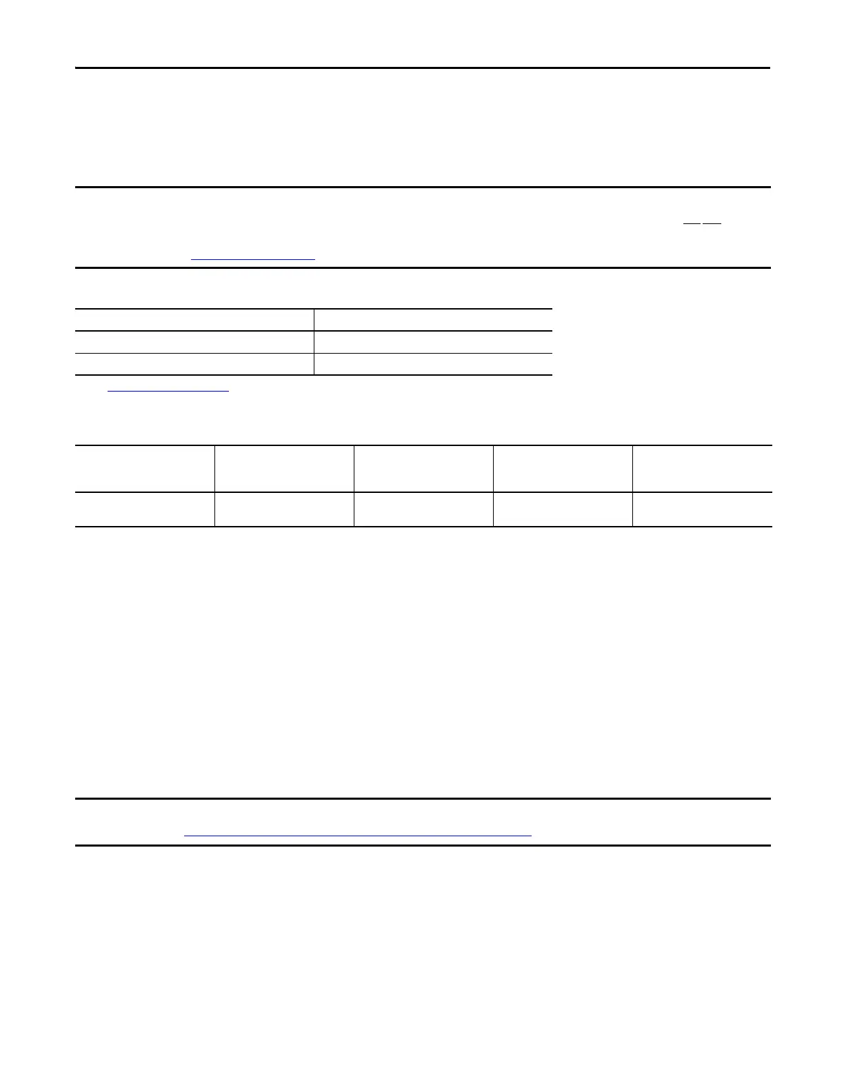
Valid Power Jumper Configurations
Power Source Jumper Positions
(1)
(1) See Power Jumper Locations on page 28.
Solid Ground All Connected
Non-solid Ground, including High-resistance Grounding All Disconnected
Drive 1
Power jumpers are
configured correctly.
Drive 2
Power jumpers are
configured correctly.
Drive 3
Power jumpers are
configured correctly.
Drive 4
Power jumpers are
configured correctly.
Drive 5
Power jumpers are
configured correctly.
❑ ❑ ❑ ❑ ❑
The drive can always be controlled by the HIM for speed, start, and stop control. If that is the case for operating conditions, proceed
to
Step 3: Power Up, Configure the Drive, and Spin the Motor Shaft on page 12.

 Loading...


