Rockwell Automation Publication 750-QS001A-EN-P - March 2015 17
Step 4: Set Up Speed Reference and Start/Stop
Step 4: Set Up Speed Reference and Start/Stop
Select the configuration according to the wiring you observed in Step 2: Validate the Drive Installation.
Input/Output Configuration Checklists
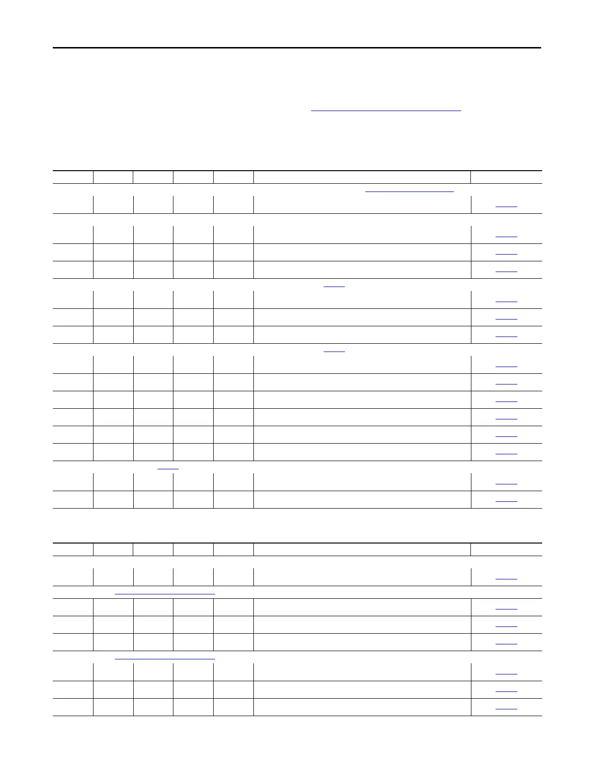
Speed Reference Source
Drive 1 Drive 2 Drive 3 Drive 4 Drive 5 Speed Reference Source Wiring Diagram
HIM (typically Port 1) (If you have a door-mounted or remote-mounted HIM on Port 2 or Port 3, refer to
Drive Device Ports on page 33 for more information.)
❑ ❑ ❑ ❑ ❑ User Adjustable at Drive
page
38
Connections on PowerFlex 753 Main Control Board (Port 0)
❑ ❑ ❑ ❑ ❑ 0…20 mA Analog Input - Unipolar Speed Reference
page 41
❑ ❑ ❑ ❑ ❑ 0…+10V Analog Input - Unipolar Speed Reference
page 42
❑ ❑ ❑ ❑ ❑ 10k Ohm Potentiometer - Unipolar Speed Reference
page 42
Connections on 11-Series Expansion I/O Module - Cat. No. 20-750-11xxx-xxxx (Port 4) (See page 32 for option module catalog numbers and port location options.)
❑ ❑ ❑ ❑ ❑ 0…20 mA Analog Input - Unipolar Speed Reference
page 45
❑ ❑ ❑ ❑ ❑ 0…+10V Analog Input - Unipolar Speed Reference
page 45
❑ ❑ ❑ ❑ ❑ 10k Ohm Potentiometer - Unipolar Speed Reference
page 45
Connections on 22-Series Expansion I/O Module - Cat. No. 20-750-22xxx-xxxx (Port 4) (See page 32 for option module catalog numbers and port location options.)
❑ ❑ ❑ ❑ ❑ 0…20 mA Analog Input - Unipolar Speed Reference at Terminals Ai0±
page
49
❑ ❑ ❑ ❑ ❑ 0…+10V Analog Input - Unipolar Speed Reference at Terminals Ai0±
page
49
❑ ❑ ❑ ❑ ❑ 10k Ohm Potentiometer - Unipolar Speed Reference at Terminals Ai0±
page
49
❑ ❑ ❑ ❑ ❑ 0…20 mA Analog Input - Unipolar Speed Reference at Terminals Ai1±
page
50
❑ ❑ ❑ ❑ ❑ 0…+10V Analog Input - Unipolar Speed Reference at Terminals Ai1±
page
50
❑ ❑ ❑ ❑ ❑ 10k Ohm Potentiometer - Unipolar Speed Reference at Terminals Ai1±
page
50
Communications Connection (See page 32 for communication option module catalog numbers and port location options.)
❑ ❑ ❑ ❑ ❑ Communication over PF755 Embedded Ethernet/IP (Port 13) (Port 13)
page 52
❑ ❑ ❑ ❑ ❑ Communication over EtherNet/IP on 20-750-ENETR Module (Port 6)
page 57
Start, Stop, and Direction Source
Drive 1 Drive 2 Drive 3 Drive 4 Drive 5 Start, Stop, and Direction Source Wiring Diagram
HIM (Port 1)
❑ ❑ ❑ ❑ ❑ User Adjustable at Drive
page
38
3-Wire Control (See 2-Wire and 3-Wire Control on page 63 for more information.)
❑ ❑ ❑ ❑ ❑ 3-Wire Control on PF753 Main Control Board
page
43
❑ ❑ ❑ ❑ ❑ 3-Wire Control on 11-Series I/O Module
page
47
❑ ❑ ❑ ❑ ❑ 3-Wire Control on 22-Series I/O Module
page
51
2-Wire Control (See 2-Wire and 3-Wire Control on page 63 for more information.)
❑ ❑ ❑ ❑ ❑ 2-Wire Control on PF753 Main Control Board
page
42
❑ ❑ ❑ ❑ ❑ 2-Wire Control on 11-Series I/O Module
page
46
❑ ❑ ❑ ❑ ❑ 2-Wire Control on 22-Series I/O Module
page 51

 Loading...


