8 Rockwell Automation Publication 750-QS001A-EN-P - March 2015
Step 2: Validate the Drive Installation
Step 2: Validate the Drive Installation
It is important that you thoroughly inspect each of your drive installations before applying power for the first time. This is
especially important if you did not personally perform the installation tasks. Satisfy yourself now that each drive is ready to
be energized when you get to
Step 3: Power Up, Configure the Drive, and Spin the Motor Shaft.
Identify Which Drive You Have
There are two types of PowerFlex 750-Series drives, the PowerFlex 753 and the PowerFlex 755. There are some important
differences between the drives that need to be considered in subsequent steps. If you don’t know how to determine what
type of drive you have, see
Determine Drive Type on page 22.
Verify Power Wiring
Visually inspect the power wiring connections to each drive. Be sure you are satisfied that the correct wires are connected to
the input terminals and to the output terminals. See
Power Wiring on page 23 for more information on where these
connections are made.
ATTENTION: To avoid an electric shock hazard, the drive must be locked and tagged before continuing Step 2: Validate the Drive
Installation. Failure to comply can result in personal injury and/or equipment damage.
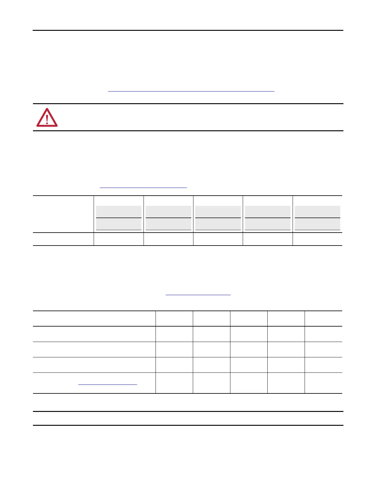
Drive/Motor Name
(example, Main Exhaust Fan)
Drive/Motor 1: Drive/Motor 2: Drive/Motor 3: Drive/Motor 4: Drive/Motor 5:
Installed Drive
❑ 753 ❑ 755 ❑ 753 ❑ 755 ❑ 753 ❑ 755 ❑ 753 ❑ 755 ❑ 753 ❑ 755
Verify Wiring
Drive 1
Wiring is Correct
Drive 2
Wiring is Correct
Drive 3
Wiring is Correct
Drive 4
Wiring is Correct
Drive 5
Wiring is Correct
AC input power is on L1, L2, L3 / R, S, T.
❑ ❑ ❑ ❑ ❑
Output motor connection is on T1, T2, T3 / U, V, W.
❑ ❑ ❑ ❑ ❑
Proper ground wire terminations at PE ground studs.
❑ ❑ ❑ ❑ ❑
If equipped, dynamic brake resistor connection is on BR1 and BR2.
If wires are present, go to Dynamic Brake Resistor on page 66 to record
dynamic brake resistor nameplate information.
❑ ❑ ❑ ❑ ❑
Rockwell Automation recommends that XLPE-type cabling be used on output of the drive.

 Loading...


