PID Set Up F-3
PowerFlex 40 Adjustable Frequency AC Drive FRN 1.xx - 7.xx User Manual
Publication 22B-UM001I-EN-E
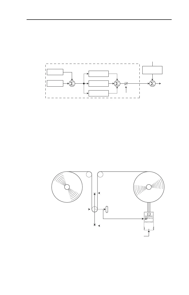
Trim Control
In Trim Control, the PID Output is added to the Speed Reference. In
Trim mode, the output of the PID loop bypasses the accel/decel ramp as
shown. Trim Control is used when A132 [PID Ref Sel] is set to option 5,
6, 7 or 8.
Example
• In a winder application, the PID Reference equals the Equilibrium
set point.
• The Dancer Pot signal provides PID Feedback to the drive.
Fluctuations in tension result in a PID Error value.
• The Master Speed Reference sets the wind/unwind speed.
• As tension increases or decreases during winding, the Speed
Reference is trimmed to compensate. Tension is maintained near the
Equilibrium set point.
–
+
PID Prop Gain
PID Loop
PID Integ Time
PID Diff Rate
PID Enabled
P038 [Speed Reference]
PID Fdbk
PID Ref
PID
Error
+
+
+
+
PID
Output
Output
Freq
+
Accel/Decel
Ramp
P038 [Speed Reference]
0 Volts
PID Feedback =
Dancer Pot Signal
10 Volts
PID Reference =
Equilibrium Set Point
22B-UM001.book Page 3 Tuesday, May 30, 2017 5:22 PM

 Loading...


