SmartCom
2
Control Installation and User Manual
10
SmartCom
2
Control Installation and User Manual
11
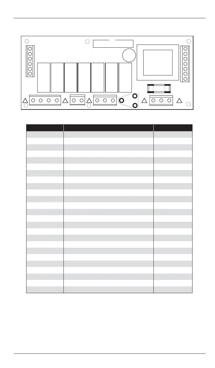
2.6 NETWORK VERSION WIRING CONNECTIONS
Terminal No: Connection Capacity mm
2
41 Vent 1 relay input (550W/low fan) 2.5
40 Vent 1 relay output (550W/low fan) 2.5
7 Heat 2 relay input (2 stage) 2.5
8 Heat 2 relay output (2 stage) 2.5
9 Burner Reset output 2.5
25 Vent 3 relay output (damper) 2.5
14 Vent 2 relay output (high fan) 2.5
5 Time relay output (CRFR) 2.5
6 Heat 1 relay output (1 stage) 2.5
1 Live supply input 2.5
2Neutral supply input 2.5
10 Flame failure input 2.5
66 Channel 1, 0~10V output (GM44) 1.5
64 Channel 1 and 2 common output 1.5
20 Channel 2, 0~10V output (damper) 1.5
C1 Comms ‘A’ input/output (M&S) 1.5
C0 Comms GND output (M&S) 1.5
C2 Comms ‘B’ input/output (M&S) 1.5
S/R0 Remote room temperature sensor ‘A’ 1.5
S/R1 Remote room temperature sensor ‘B’ 1.5
D0 Remote duct temperature sensor ‘A’ 1.5
D1 Remote duct temperature sensor ‘B’ 1.5
B1 Remote On input (BMS ON input) 1.5
B0 Remote common (output to BMS) 1.5
B2 Remote input (see 4.4) 1.5
Figure - Network version PCB connections
LIVE
FUSE
NEUT
B2
B0
B1
D1
D0
S/R1
S/R0
66
64
20
C1
C0
C2
! ! !
41 40
7
8
9
25 14
5
6 1/L
2/N
10
! !
A terminal block is supplied to enable multiple connections to BO/B2 as detailed in product
wiring connections.
0-10V outputs and remote switch inputs should be connected by 0.75mm
2
cable of maximum
length 100m.
The remote temperature sensor may be placed at a distance of up to 100m (maximum) from the
control unit, using screened 0.75mm
2
cable to improve noise rejection. Connect the screen to
terminal B0. Master-slave communication is by screened twisted pair cable, RS 485 compatible,
such as Belden 9841. Maximum overall system length is 500m. Connect screens to B0 and C0.
All sensor and signal wiring should be kept separate from mains wiring to minimise noise pick-up.
3 OPERATING INSTRUCTIONS
3.1 The Buttons
The ten buttons have the following functions:
LOCKOUTPLUS
MINUS
OK
UNDO
VENT ONL Y
SETTINGS
OVERTIME
HOLIDAY
CHECK TEMP
12
6
39
PLUS
Increase a value
VENT ONLY
Initiate a period of forced
vent operation
MINUS
Decrease a value
OVERTIME
Initiate or quickly extend a
period of heating
OK
Accept a newly entered value
HOLIDAY
Set the control to holiday
mode
UNDO
Press once to cancel overtime, vent,
exam, off and holiday modes or a newly
entered value not yet OK’d
CHECK TEMP
Toggle the display to show
the temperatures
SETTINGS
12
6
39
Initialise and step through: off mode,
exam mode*, setting clock, heating
control modes, and programming
LOCKOUT
Clear a fl ame failure lockout
Note:
If no keypad action takes place for 60 seconds, the current selection is cancelled and
the display returns to day and time and previously set operating mode.
* Exam Heating mode (EH) will appear only if selected in the engineer functions.
3.2 The Display
During normal operation the time and day will be displayed as well as the operating
mode that has been set. The screen below shows the operating mode; [FROST]
[ONLY].
Figure - Frost Mode
 Loading...